My Gainclone Integrated Build (Peter daniel/Audiosector boards)
Dear Friends,
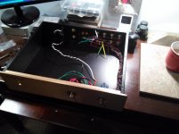
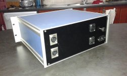
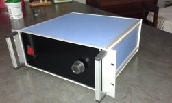
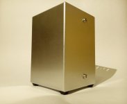
I decided to post a record of my Gainclone integrated build which I completed over the 4th of July Weekend. It is an integrated amplifier with 4 inputs using Peter Daniel's boards.
I have used a dual mono construction throughout with 2x160VA (2x24v) transformers, a 51K stepped attenuator and a larger enclosure.
As you can see from the photos the arrangement is relatively traditional, and this is more for convenience and inteference management than any aesthetic consideration.
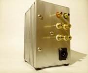
I've also added a DPST switch to the rear panel in order to be able to isolate both the live and neutral when de-energizing the amplifier.
Dear Friends,
I decided to post a record of my Gainclone integrated build which I completed over the 4th of July Weekend. It is an integrated amplifier with 4 inputs using Peter Daniel's boards.
I have used a dual mono construction throughout with 2x160VA (2x24v) transformers, a 51K stepped attenuator and a larger enclosure.
As you can see from the photos the arrangement is relatively traditional, and this is more for convenience and inteference management than any aesthetic consideration.
I've also added a DPST switch to the rear panel in order to be able to isolate both the live and neutral when de-energizing the amplifier.
Attachments
My Gainclone Integrated Build (Peter daniel/Audiosector boards)
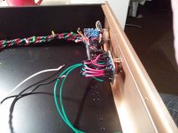
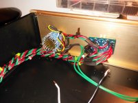
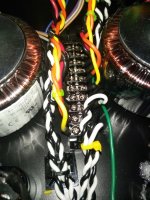
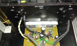
Here are some close up shots of the selector switch which I obtained from Glass Ware Audio - the select 5 switch. The switch was a real find as it comes with a nice PCB which makes construction very easy and it also features separate ground switching for each source (although I elected to use a common ground for the inputs) Beside it you can see my 51K stepped attenuator fitted in place. I obtained this from ebay about 10 years ago and it has been sitting in a box awaiting a project ever since. Time will tell if it's any good.
Here are some close up shots of the selector switch which I obtained from Glass Ware Audio - the select 5 switch. The switch was a real find as it comes with a nice PCB which makes construction very easy and it also features separate ground switching for each source (although I elected to use a common ground for the inputs) Beside it you can see my 51K stepped attenuator fitted in place. I obtained this from ebay about 10 years ago and it has been sitting in a box awaiting a project ever since. Time will tell if it's any good.
Attachments
My Gainclone Integrated Build (Peter daniel/Audiosector boards)
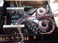
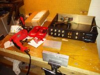
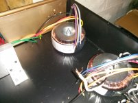
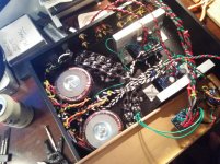
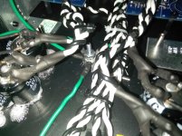
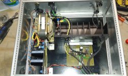
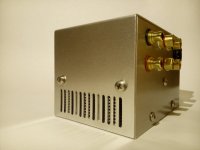
Here are some images showing my test arrangment for the amplifier, I wanted to make sure I had the optimum arrangement for all the internal components. In particular I wanted to make sure I kept the power section as far away from the signal section as I could. From right to left you can see: firstly the two toroidal transformers, the main capacitor banks (I decided to add a considerable degree of capacitance to the power supply) the amplifier and rectifier boards and the heatsinks (I am using some heavy aluminum bar) and the path of the signal cabling. I shall be trying to keep all the power cables perpendicular to the signal cabling as much as possible to minimize interference.
Here are some images showing my test arrangment for the amplifier, I wanted to make sure I had the optimum arrangement for all the internal components. In particular I wanted to make sure I kept the power section as far away from the signal section as I could. From right to left you can see: firstly the two toroidal transformers, the main capacitor banks (I decided to add a considerable degree of capacitance to the power supply) the amplifier and rectifier boards and the heatsinks (I am using some heavy aluminum bar) and the path of the signal cabling. I shall be trying to keep all the power cables perpendicular to the signal cabling as much as possible to minimize interference.
Attachments
My Gainclone Integrated Build (Peter Daniel/Audiosector boards)
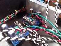
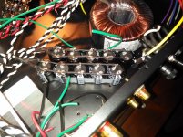
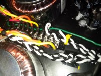
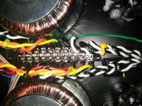
Here are some additional images showing the arrangement in more detail. In the first image you can see the capacitor bank for the right channel. I decided to use 23,500uF per rail for a total of 47,000uF per channel. This should ensure little or no ripple or interference from the electrical mains. I have just used the subberizing section of the PCB for the blocking capacitor and resistor. If necessary, once the amplifier is operational, I can fit additional blocking capacitors and resistors to these banks.
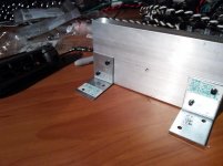
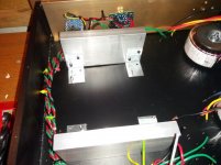
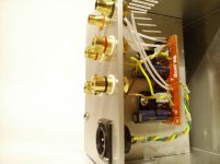
In the next photo you can see how I propose to place the amplifier boards and rectifiers. I shall be drilling and tapping the aluminum bar for M3 bolts and attaching the brackets and boards that way. PSU cabling will be kept perpendicular to the signal cabling and I shall be routing the PSU cables to the bottom of the enclosure and the incoming and outgoing signal cables shall be routed at high level in the case at 90 degrees.
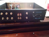
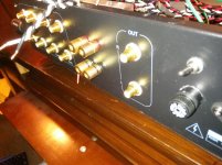
In the last photo you can see the RCA input sockets and the common ground buss. I have used coloured cable ties on the sockets and input cables in order to wire up the selector switch to the correct inputs.
Here are some additional images showing the arrangement in more detail. In the first image you can see the capacitor bank for the right channel. I decided to use 23,500uF per rail for a total of 47,000uF per channel. This should ensure little or no ripple or interference from the electrical mains. I have just used the subberizing section of the PCB for the blocking capacitor and resistor. If necessary, once the amplifier is operational, I can fit additional blocking capacitors and resistors to these banks.
In the next photo you can see how I propose to place the amplifier boards and rectifiers. I shall be drilling and tapping the aluminum bar for M3 bolts and attaching the brackets and boards that way. PSU cabling will be kept perpendicular to the signal cabling and I shall be routing the PSU cables to the bottom of the enclosure and the incoming and outgoing signal cables shall be routed at high level in the case at 90 degrees.
In the last photo you can see the RCA input sockets and the common ground buss. I have used coloured cable ties on the sockets and input cables in order to wire up the selector switch to the correct inputs.
Attachments
My Gainclone Integrated Build (Peter Daniel/Audiosector boards)
In these photos you can see that I have installed the pre-amplifier out sockets in case I decide to convert this enclosure to an active buffer/pre-amplifier at a later date (relocating the monoblock power amps to another case). I shall be using the stepped attenuator as a passive pre-amp to begin with (I have had good results in the past with this arrangement) but if I feel I need more front end gain I can always build a B1 buffer or an Aikido valved pre-amplifier.
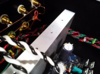
In the next photo I am drilling and tapping the aluminum bar for the mounting of the Audiosector board and fitting the bar to the enclosure.
In the last photo you can see all the tapping complete and the mounting brackets attached with M3 bolts.
In these photos you can see that I have installed the pre-amplifier out sockets in case I decide to convert this enclosure to an active buffer/pre-amplifier at a later date (relocating the monoblock power amps to another case). I shall be using the stepped attenuator as a passive pre-amp to begin with (I have had good results in the past with this arrangement) but if I feel I need more front end gain I can always build a B1 buffer or an Aikido valved pre-amplifier.
In the next photo I am drilling and tapping the aluminum bar for the mounting of the Audiosector board and fitting the bar to the enclosure.
In the last photo you can see all the tapping complete and the mounting brackets attached with M3 bolts.
Attachments
My Gainclone Integrated Build (Peter Daniel/Audiosector boards)
Now I can begin the mechanical phase of this project. This will involve the fitting of all the hardware, the preparation of the star ground point an finishing off the enclosure.
In the first photo you can see the two transformers are now fitted.
In the next, the holes for the heatsinks have been drilled and test fitted.
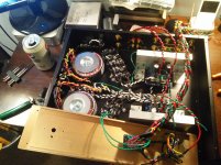
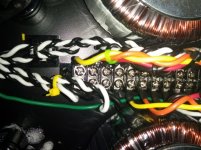
In the next photo the boards have been fitted to the heat sinks, the capacitor banks have been added, the star ground is located in the centre of the enclosure and a terminal strip has been located between the transformers for the transformer/mains/PSU cable connections.
At this point the amplifier is mechanically complete and I just need to complete the signal input connections and the in/out connections of the amplifier boards.
Now I can begin the mechanical phase of this project. This will involve the fitting of all the hardware, the preparation of the star ground point an finishing off the enclosure.
In the first photo you can see the two transformers are now fitted.
In the next, the holes for the heatsinks have been drilled and test fitted.
In the next photo the boards have been fitted to the heat sinks, the capacitor banks have been added, the star ground is located in the centre of the enclosure and a terminal strip has been located between the transformers for the transformer/mains/PSU cable connections.
At this point the amplifier is mechanically complete and I just need to complete the signal input connections and the in/out connections of the amplifier boards.
Attachments
My Gainclone Integrated Build (Peter Daniel/Audiosector boards)
The final stage of the build has now been reached.
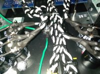
The first photo shows the connection of signal cables and the final dressing of cables.
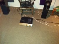
I must apologize for the bad quality of the final two photographs, this could not be helped as I don't have a digital camera, other than my mobile phone.
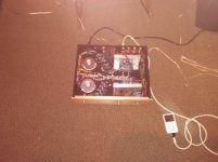
The first photo shows the amplifier on test, using the digital output of an iPod as the source. I haven't got the figure for DC offset and voltages with me, but I remember the DC offset was no more than 30mV on either channel at full volume on the attenuator. The voltages on the PSU side were also very good, making about 34vDC supplied to the amp.
The final photo shows the amplifier connected to my Kef Q30 speakers, again using the iPod as a source.
Listening notes from this build:
1. This amplifier is completely silent. There is no ground hum (that I can detect) at all, total silence between tracks.
2. This amplifier is completely silent electro-mechanically also. There is absolutely no mechanical hum from the transformers - none whatsoever.
3. Having 94,000uF capacitance on the PSU means that the amplifier continues to play for about 90 seconds to 2 minutes after the electrical supply is disengaged. I may have to add additional bleeder resistors. I shall monitor this situation.
4. Sonically, this amplifier is superb. The blackness between notes is palpable; on guitar and voices, the reproduction is stunning. With the larger capacitance in the PSU, bass notes have a visceral feel and real weight. The speed of this amplifier is also quite remarkable.
On playback I find I become lost in the music and as the amplifier breaks in over the next few weeks I expect this phenomenon be become even more noticeable.
Caveats:
1. I discovered that my stepped attenuator has at least one bad resistor or solder joint, so I shall have to make a repair or replacement. Luckily, since I used an attenuator, all the other settings are still available - it's only the faulty step which I cannot use.
On a final note, I have now connected my amplifier to my primary digital source: A Raspberry Pi 2 running PiMusicbox connecting through a HIFIman HM-101 USB Dac (PCM2702) so I can control and playback my entire music collection using my android phone as the remote control. It even allows for control of the volume from the phone (it attenuates the output of the dac)
On a final note, this was a fun project to do, it only took about 20 hours of actual work, most of the time was spent waiting for parts and materials to arrive.
I would like to thank Peter Daniel for his wonderful boards, as they made the build so much easier, and everyone else here at DiyAudio for the inspiration.
The final stage of the build has now been reached.
The first photo shows the connection of signal cables and the final dressing of cables.
I must apologize for the bad quality of the final two photographs, this could not be helped as I don't have a digital camera, other than my mobile phone.
The first photo shows the amplifier on test, using the digital output of an iPod as the source. I haven't got the figure for DC offset and voltages with me, but I remember the DC offset was no more than 30mV on either channel at full volume on the attenuator. The voltages on the PSU side were also very good, making about 34vDC supplied to the amp.
The final photo shows the amplifier connected to my Kef Q30 speakers, again using the iPod as a source.
Listening notes from this build:
1. This amplifier is completely silent. There is no ground hum (that I can detect) at all, total silence between tracks.
2. This amplifier is completely silent electro-mechanically also. There is absolutely no mechanical hum from the transformers - none whatsoever.
3. Having 94,000uF capacitance on the PSU means that the amplifier continues to play for about 90 seconds to 2 minutes after the electrical supply is disengaged. I may have to add additional bleeder resistors. I shall monitor this situation.
4. Sonically, this amplifier is superb. The blackness between notes is palpable; on guitar and voices, the reproduction is stunning. With the larger capacitance in the PSU, bass notes have a visceral feel and real weight. The speed of this amplifier is also quite remarkable.
On playback I find I become lost in the music and as the amplifier breaks in over the next few weeks I expect this phenomenon be become even more noticeable.
Caveats:
1. I discovered that my stepped attenuator has at least one bad resistor or solder joint, so I shall have to make a repair or replacement. Luckily, since I used an attenuator, all the other settings are still available - it's only the faulty step which I cannot use.
On a final note, I have now connected my amplifier to my primary digital source: A Raspberry Pi 2 running PiMusicbox connecting through a HIFIman HM-101 USB Dac (PCM2702) so I can control and playback my entire music collection using my android phone as the remote control. It even allows for control of the volume from the phone (it attenuates the output of the dac)
On a final note, this was a fun project to do, it only took about 20 hours of actual work, most of the time was spent waiting for parts and materials to arrive.
I would like to thank Peter Daniel for his wonderful boards, as they made the build so much easier, and everyone else here at DiyAudio for the inspiration.
Attachments
A very nice build, dpogorman. One thing though worries me; those speaker terminals are grouped pretty tight and their are full metal, so they could be short circuited very easily, if something conductive falls on them. Yes, I have lost one NAD T163 in an accident like that...
My Gainclone Integrated Build (Peter Daniel/Audiosector boards)
I am a little concerned about this and before I fit the amplifier into my main system I may replace the speaker connections - or sheath them to ameliorate the risk of a short circuit. I use banana plugs for the connection to the amplifier and spade connectors at the speaker end, with heat shrink placed at the connection points. This should prevent any stray strands of wire from making any unwanted or unsafe contacts.
Thanks for your feedback and concern.
Dale.
A very nice build, dpogorman. One thing though worries me; those speaker terminals are grouped pretty tight and their are full metal, so they could be short circuited very easily, if something conductive falls on them. Yes, I have lost one NAD T163 in an accident like that...
To each their own but I turn off my equipment when I make physical changes... However out of caution I also use insulated binding posts...
My Gainclone Integrated Build (Peter Daniel/Audiosector boards)
I would take it for granted that the system would be de-energized during a cable change, I assumed Mr. Tuo was concerned something could fall over the posts during usage.
If anyone is in doubt, I always power off the unit and allow for the capacitors to discharge before making any changes to a unit.
To each their own but I turn off my equipment when I make physical changes... However out of caution I also use insulated binding posts...
I would take it for granted that the system would be de-energized during a cable change, I assumed Mr. Tuo was concerned something could fall over the posts during usage.
If anyone is in doubt, I always power off the unit and allow for the capacitors to discharge before making any changes to a unit.
Troy: yes, I do that too, but this time there was a guest in my house, who was too quick to do it before I had time to react. We had a nice evening with SingStar and then he wanted to disconnect the microphone IR receiver from the PS3. And he did it before turning off the system and starting from the wrong end, so that the one end of the USB cable was still attached to the powered system at PS3 and the free end swung into the speaker terminals... In the end his insurance did pay for the damage.
Accidents tend to happen without warning is the lesson here.
And nowadays I also use isolated bananas with my speaker / amplifier terminals.
Accidents tend to happen without warning is the lesson here.
And nowadays I also use isolated bananas with my speaker / amplifier terminals.
Last edited:
Troy: ...there was a guest in my house, ... he wanted to disconnect the microphone IR receiver from the PS3. And he did it before turning off the system and starting from the wrong end, so that the one end of the USB cable was still attached to the powered system at PS3 and the free end swung into the speaker terminals...
Never let strangers or untrained people unplug anything from your devices. Your friend should have asked permission and waited to receive it before acting. That was very rude of him.

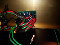
Close up shots of the terminal strip and star earth
Dear Kokanee,
Here are some photographs of the terminal strip and star grounding in the amplifier.
dpogorman,
Would you please post a close up of the star grounding and the terminal strip. Kind of hard to see them with all the wire.
Thanks, and a great build
Myles
Dear Kokanee,
Here are some photographs of the terminal strip and star grounding in the amplifier.
Attachments
My contribution:
LM3876's in a DIN case I salvaged from an old guy who had to clean out his garage...
Heatsink is from an old Sperry Mainframe bit
My son did the PCB layout and construction.
It was built to serve as a small PA amp when performing in small venues, hence the XLR inputs and SpeakOn sockets.
Some guys were sceptical about the sound quality, but they were blown out of the water.
It gets linked to a small mixing desk (Behringer 1602) and performs really well!
Attachments
dual86
Hey guys,
after some time I finished my amplifier, though I still need to make matching unit for the power supply, hopefully by the end of the summer.
It is a stereo PCB designed by me with some help from other forum members.
Best Regards,
Aleš
Hey guys,
after some time I finished my amplifier, though I still need to make matching unit for the power supply, hopefully by the end of the summer.
It is a stereo PCB designed by me with some help from other forum members.
Best Regards,
Aleš
Attachments

- Home
- Amplifiers
- Chip Amps
- Chip Amp Photo Gallery