Why to enhance a chip amp?
The trouble with these amps they are designed as opamps for stability and easy for use. The downside is very low NFB at high frequencies. In modern amps with two pole OLG, one can get over 50db NFB@20khz, while chip amps hardly reaches 30db. This results in low resolution amplifier with bad reproduction of complex vocals or large orchestras.
A simple way to correct, is to add a MOSFET to pump extra gain at OLG. The chip amp is used as its highest possible IV converting gain and the MOSFET converts the error voltage into current.
The universal circuit is shown bellow using LM3886 as simulation model compared to its application circuit. The Loop gain curves show how the initial 25db NFB@20khz leaps to 60db with MOSFET. The distortion is not implemented but the noise is. Comparing the output noise at 1khz, the 41.7uv of the initial circuit gets reduced to 0.7uv with MOSFET, this is 58 times lower which I estimate the distortion of the chip alone gets also reduced by the same factor.
I tried this circuit on Chinese TDA2050-LM1875, TDA7294 and LM3886. The best sounding I got is with 7294. Besides getting very smooth high frequencies, it has a wide, generous midrange that reminds me 45rpm records. With 3886, every time I tried this chip in composit, the voices goes back stage, with MOSFET, I got the worst ever of such type of sound. If I don't like it, many consider it better as they call it 3D sound or holographic.
The 7293 has 0.005%THD 1khz 5W, it gets reduced to 0.0001% to add the THD of 2N7000 of 0.0005% it should result less than 0.0006% in total.
The power supply will be a semi floating type for better bass using conventional psu, with SMPS, the positive input of the chip needs to be referenced to a virtual ground(2x10k resistors from rails).
I will design a PCB for 7293.

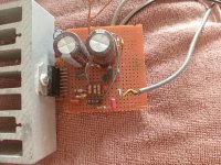
This is the prototype, it needs to add standby delay to let the C1 charge before startup and avoid plop.
You must specify the load impedance, the power you need and the type of PSU, linear or SMPS you will use.
I can also make it dual 7293 parallel.
You must specify the load impedance, the power you need and the type of PSU, linear or SMPS you will use.
I can also make it dual 7293 parallel.
Attachments
I will try the semi floating supply.
https://www.diyaudio.com/community/threads/semi-floating-split-supply-vs-standard-psu.403257/
With solid ground, the bass gets weak with tda7294 and LM3886, not with the Chinese cheap LM1875/TDA2050.
The advantage of the semi floating supply, it do not require speaker protection.
https://www.diyaudio.com/community/threads/semi-floating-split-supply-vs-standard-psu.403257/
With solid ground, the bass gets weak with tda7294 and LM3886, not with the Chinese cheap LM1875/TDA2050.
The advantage of the semi floating supply, it do not require speaker protection.
Here how this amp is born.
https://www.eevblog.com/forum/projects/how-to-make-chip-amps-sound-as-beautiful-as-se-triodes-do/
https://www.eevblog.com/forum/projects/how-to-make-chip-amps-sound-as-beautiful-as-se-triodes-do/
I managed to get full bass with standard psu. It is a mater of ground scheme. The start up plop needs 3 resistor and a capacitor.
I will travel in few days so I am designing the PCB online EASY EDA with smartphone.
You must be patient as it may take 2-3 months to make and check the prototype.
I will travel in few days so I am designing the PCB online EASY EDA with smartphone.
You must be patient as it may take 2-3 months to make and check the prototype.
I will make at least 3 PCBs as I am not sure what is the real reason that chip amps get low bass. The most significant is the magnetic field cancelation. To pass high currents through thin wires, the magnetic field should be canceled out. This why the output is sandwiched between the +/- rails. The problem is the ground that must come sandwiched with the supplies and pair with the output so that the magnetic field of the output and the ground cancel each other. The signal ground is taken just at the point where the output meets the ground to go joint towards the socket.
The mute is useless as I use the negative input. The standby is absurd as it needs only 1.5v max to switch on but the standby ground, that is the reference can be adjusted. In order not to use 50v 470uF capacitor but just 100uF 16v tomorrow I will try to make the standby delayed only a LED voltage more than the standby ground which will be about 8v.
I always get amazed when I switch on this amp. The sound is so generous in midrange. I listened Niel Diamond with so profound masculin voice, I don't have any amp among dozens that have this type of sound. I hope the original TDA7293 will be the same.
Last edited:
Single vs double tda7293.
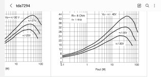
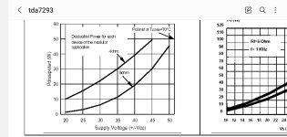
The tda7294 power dissipation curve shows for +/-35v 8ohm is 32W max.
The tda7293 double shows 12W each for 8ohm +/-35 that is 24W. This means the heatsink for 2 chips paralleled is smaller by 33% for the same output power than a single chip. This why I am interested in the modular "paralleled " mode.
Attachments
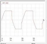
I made a plop free start up that resets very fast. Now it has slight clac on shut down probably the bootstrap capacitor discharging.
Bellow are kicad files with .txt extension to wipe off. The values are exactly what I have on the working model.

Bellow are kicad files with .txt extension to wipe off. The values are exactly what I have on the working model.
Attachments
Last edited:
Bellow is a sketch of PCB rails, ground and output, two layers.
The star point lies where the 1000uF capacitors get ground and the speaker ground seperates. The ground AC currents are only after separation and the DC is present from connector to star point.
The long leads of the chip are oblique bent, these must be orthogonal to sit flat on the PCB.
A PTC can be added on the ground DC path that can protect the speaker but one of 1000uF is sacrificed.
Last edited:
- Home
- Amplifiers
- Chip Amps
- Chip amp + MOSFET composite