Why not just do a near-field measurement (with woofer and port responses scaled and summed together) for the response up to about 200Hz, then splice that to a far field gated measurement above 200 Hz ?
There's really no need to measure the bass response far field these days, as long as the software supports being able to sum the impulse responses together for the woofer and port, and then splice the near-field FR graph thus produced with a separate far field FR measurement. Plenty of current easily available software such as ARTA can do this.
With a large anechoic chamber good down to 70Hz you could use a rather long gate time for the far field measurement compared to those trying to do the same thing in a normal room, so you could get excellent accuracy above the splicing point.
Also, one thing that puzzles me about your graphs is that they all have a linear frequency axis. It's far, far more useful and standard practice to use a logarithmic axis for frequency as well as amplitude. Using a linear axis can be visually somewhat misleading, especially at bass frequencies which get crammed into the far left hand side of the graph on a linear scale.
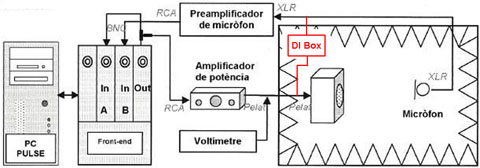
Here you go the diagram setup of the measure.
i'll try to go tomorrow, and see if its open, and measure the impedance.
I checked the setup i did...and i think the setup of the PulseLabshop is all ok....
White noise generator, Freq Response H1 (microphone,Speaker), Coherence function ( to check that measure is correct...), Span i will shorter it") ,... humm.. dunno what else...
,... humm.. dunno what else...
About the 250Hz to adjust, how much dB's should i look for then to adjust for the sensivity measure??
Thx for your help again
An externally hosted image should be here but it was not working when we last tested it.
i'll try to go tomorrow, and see if its open, and measure the impedance.
I checked the setup i did...and i think the setup of the PulseLabshop is all ok....
White noise generator, Freq Response H1 (microphone,Speaker), Coherence function ( to check that measure is correct...), Span i will shorter it
,... humm.. dunno what else... About the 250Hz to adjust, how much dB's should i look for then to adjust for the sensivity measure??
Thx for your help again
Interesting statement you make, you are measuring with white noise. Maybe you should use Pink Noise next time for measuring the frequency response of a loudspeaker and your graphs will look different
250Hz calibration is only possible if you have a 250Hz reference source such as a Piston calibrator or a Bruel & Kjaer calibrator system. Could you also tell what brand and type of measuring mic you are using?
About your question if the room can be used for measurements below 70Hz. Yes it can only the measurements are not 100% reliable and will be influenced by the acoustics of the room. One of the reasons why you need to measure from corner to corner instead of parallel to the walls as you did.
Simon, Pulse labshop reads out standard in linear graphs because the equipment is for multi-purpose use in other engineering areas. So change that in logarithmic Endrik and your readouts are more confirm audio standards.
Last edited:
Hi, i just finished my first design, a 18'' Fane Colossus 18XB in a 221L bass reflex box i designed.
Now i had the oportunity to check the response of my speaker in an anechoic chamber, and see the frequency response.
I'm trying different configurations of damping material inside and measuring the frequency response, so i can see and measure wich configuration will be best.
Now i upload the graphics, and when i get home i'll upload some pictures about the mounting and the box.
1.-
An externally hosted image should be here but it was not working when we last tested it.
Blue line is with full damping material // green line no damping material
2.-
An externally hosted image should be here but it was not working when we last tested it.
Blue line is with full damping material // green line with half damping material
I haven't got time to try more configurations, but hope i wil try to convince them to let me have some more fun.
Do you think is it good enough? Do you think i made a crappy design and should throw it to the bin? Any advices??
One question i have is, someone told me something about....(can't remember wel..) that if you want to measure frequency response of a subbass speaker, you have to be at "far field", not at 1m, like i've been doing. Can anyone explain me this please?
Here are the freq response with the hole span:
1.- No damping material
An externally hosted image should be here but it was not working when we last tested it.
2.- Half loaded damping material (BACK AND UP)
An externally hosted image should be here but it was not working when we last tested it.
3.- Fully loaded with damping material
An externally hosted image should be here but it was not working when we last tested it.
Thx for your help in advance.
Don't be cruel, its my very first toy i make
pd: measures done with good microphone (omnidir & flat resp) and Pulse Labshop
The response is very disappointing. Looks like the F3 is around 130 to 150 hz. Response falls very fast below 100 and is gone by 50. If this is a ported system, I think the box is much too small, tuning all wrong. Check with the driver manufacturer. They usually have good advice on the best box dimensions and recommended port diameter and length for their drivers.
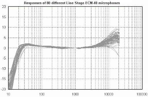
Microphone data sheet (IMG Stage line ECM-40)
http://www.content.ibf-acoustic.com/catalog/ddownload/ecm-40.pdf
Preamp ( IMG Stage line MPA-102)
http://www.monacor.de/de/FLE/MPA102.pdf
sorry i said a mystake, i did it with pink noise. I wrote the answer quickly.
http://www.content.ibf-acoustic.com/catalog/ddownload/ecm-40.pdf
Preamp ( IMG Stage line MPA-102)
http://www.monacor.de/de/FLE/MPA102.pdf
sorry i said a mystake, i did it with pink noise. I wrote the answer quickly.
Hi,
today i had some time to measure with this setup the impedance of the 2 drivers i have (Fane Colossus 18XB) and after measure the impedance of the drivers mounted in the same box.
Setup, generating a sinwave and first calibrating the voltage to 0,01V with the 10Ohm resistor:
Finally i started writting down, one by one the values, and put it in an excel.
Driver 1 Fs = 47Hz , Fb= 39-41 Hz /////// Driver 2 Fs= 40Hz , Fb= 39-41Hz
There is only values until 100, because i hadn't had too much time, and i had to do it quickly, and no time to write down 1000 values
I see that the drivers have different Fs, they end up having nearly the same Fb. But the impedance curve of the driver's alone, they differ quite a lot. Can it be that one of them is broken? Or there will never be a identical driver?? I haven't calculated the T/S parameters...But the Fs at the datasheet tells Fs=33Hz, here i see it isn't that close.....
What do you think??
thx again for your help really appreciate your time
today i had some time to measure with this setup the impedance of the 2 drivers i have (Fane Colossus 18XB) and after measure the impedance of the drivers mounted in the same box.
Setup, generating a sinwave and first calibrating the voltage to 0,01V with the 10Ohm resistor:
An externally hosted image should be here but it was not working when we last tested it.
Finally i started writting down, one by one the values, and put it in an excel.
An externally hosted image should be here but it was not working when we last tested it.
Driver 1 Fs = 47Hz , Fb= 39-41 Hz /////// Driver 2 Fs= 40Hz , Fb= 39-41Hz
There is only values until 100, because i hadn't had too much time, and i had to do it quickly, and no time to write down 1000 values
I see that the drivers have different Fs, they end up having nearly the same Fb. But the impedance curve of the driver's alone, they differ quite a lot. Can it be that one of them is broken? Or there will never be a identical driver?? I haven't calculated the T/S parameters...But the Fs at the datasheet tells Fs=33Hz, here i see it isn't that close.....
What do you think??
thx again for your help
really appreciate your time
Last edited:
Endrek, you could try a DI box and measure the output signal of your amp on a 8Ohm dummy load (instead of the loudspeaker). That way you can see if the signal is flat.
i will try to do it as soon as they let me and tell you
thx for all
by the way...... about the Cut frequency of the anechoic chamber...... What can i do?? just know that my measure won't be reliable below 70? Can i do somethin like.....the transfer function of the room? and then convulotion with the pink noise(input)....or something like that??
H(f) = Y(f)/X(f) ?? i don't know how this really works.... but i saw in a theory book....
Last edited:
One of the difference between pro drivers and semi pro is the ‘large’ tolerance of specs you’ll find in semi pro stuff. But what you measured is like 7Hz for driver 2 and 14Hz for driver 1, from the 33Hz specs! That is offset off 21% for the red and 42% for the blue. I think that is even for a brand as Fane a little too large for an "acceptable tolerance".
But to be honest last time I saw Fane in a pro brand cab is looooong time ago...
Btw what is the resistance of the VC's?
But to be honest last time I saw Fane in a pro brand cab is looooong time ago...
Btw what is the resistance of the VC's?
Last edited:
i think You should calculate TS parameters to verify what You based Your design on.
But i do not think there is too mutch room for improvements.
Maybe a subwoofer EQ could help You out, if the drivers can -and why could they not- handle the extra load.
EQ with what? with the DSP i bought?? I have the dBx DriveRack PA+.
One of the difference between pro drivers and semi pro is the ‘large’ tolerance of specs you’ll find in semi pro stuff. But what you measured is like 7Hz for driver 2 and 14Hz for driver 1, from the 33Hz specs! That is offset off 21% for the red and 42% for the blue. I think that is even for a brand as Fane a little too large for an "acceptable tolerance".
But to be honest last time I saw Fane in a pro brand cab is looooong time ago...
Btw what is the resistance of the VC's?
What is VC's??? voltage counter??? If so... i didn't measure the impedance, i only know it is a "fluke 187".
I did measure the resistance of the amplificer (Ecler XPA 3000) but didn't thought it was representative...(It wasn't stable at any time...but it was below 1Ohm) Will it influence so much???
VC's = Voice coils
sorry for my ignorance
VC'c
are "nearly" the same... Re1=6,88Ohm and Re2=6,79OhmWell, that close huh, in that case it looks like the mechanical tolerances are somehow way off. I'm afraid Arty has a good point there, that there is not much room for real improvement or you have to measure all specs for each driver separately and re-design for each driver.
could be, but i do not think so. both drivers are quite far from the datasheet specs, at lest Fs wise.
Best would be to.. simpl try and live with it, and make an EQ for eatch driver.
Just be sure to let them run a bit, probably once both gets broken in the EQ would need revision.
Best would be to.. simpl try and live with it, and make an EQ for eatch driver.
Just be sure to let them run a bit, probably once both gets broken in the EQ would need revision.
are the broken in?
maybe that explains the differnces
What do you mean?? broken what?¿?
So.... about the freq response.....
Can it be posible that difference of dB's between 50 Hz and 200 Hz is due to the "anechoic chamber" that isn't so anechoic below the cut off frequency, right?
So reflections make an increase of the energy at upper frequencies, and my measure isn't reliable.
Conclusion....i need to do the measure outside?
Thanks for all your help
- Status
- This old topic is closed. If you want to reopen this topic, contact a moderator using the "Report Post" button.
- Home
- Loudspeakers
- Subwoofers
- Check my First Box & Measure in anechoic chamber