Jensen: I should have mentioned, main reason the sink on the top will help, is because you can still put a sink on bottom as well, so you get 2x crappy cooling = slightly less crappy cooling
Btw. Tracking says you haven't picked up the pcbs from your local post office yet.
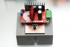
I see what you did there. It looks like they do at least leave the solder mask off of the board for the bottom heatsink version though, so slightly more effective, maybe, kind of, but not really without the thermal vias.
Yeah I am hoping to grab the boards on Friday, post office is closed by the time I get out of work most of the time.

EDIT: There is also the super duper "1200W" boost only, which will do 20A
http://www.ebay.com/itm/1200W-20A-D...562420?hash=item2a57cb3834:g:dGoAAOSwQTVV7gck
Back on topic.
Is the TPA3110 based on the same silicon as the TPA3118/TPA3116? I ordered a pair of these with my last ebay purchase just to try out. Looks very similar to the 3118 board, but the output filter layout looks a bit different. (No post inductor snubber?)
http://www.ebay.com/itm/281958336298?_trksid=p2060353.m2749.l2649&ssPageName=STRK:MEBIDX:IT
Last edited:
Hell yes on the boat, good pickup there, me being sailormanbigd! The sole reason for the build is boat and beach, outdoor duty here in West Central Florida. North and west of Tampa, North of Clearwater about 15-20 miles. The boxes will be made from pink foam, sealed and i will prob fiberglass them for lonjevity and strength? the coax drivers are listed as water-resistant formerly for wakeboard design. Okay loud with decent sq is goal. No good loud if lousy sound. So I will probably mount the amps and batts in a separate box and piggy back to the speaker enclosure S. Can't ventilate due to likely water/moisture consideration. Thanks for the aluminium bar suggestion and will probably have the AL exposed outside the electronic box for heat dissipation? So which dc-dc converter? So much foreign language, buck/boost et al. This is budget build - the coax drivers were 10.50$ each x4, amps 6.50$ea x2, Bluetooth aptx 4.0 $6or$8? 12Vx5hr SLA at around $12 ?= 42+13+8+24==87$ so far. Don't tell the old lady!!!!!!! Disco/reggae beach party =priceless!!
As long as you are confident in your ability to seal out water and salt, and/or you don't care if the electronics corrode out in a few years, I would go with this DC-DC as a cost effective, yet not totally garbage out of the box option. Just mount it with the amplifier boards. Using an aluminum panel as an exposed surface outside is a good idea to get some heat out (either make one of the box walls out of aluminum, or like you said, have an aluminum bar coming out of the foam box and bolt whatever gets hot to that.)
1pc LTC3780 Automatic Lifting Pressure Constant Voltage Step Up Down 10A 130W | eBay
If you want something that will last you well beyond everything else in that setup, go with the Victron Orion posted by t-head.
1pc LTC3780 Automatic Lifting Pressure Constant Voltage Step Up Down 10A 130W | eBay
If you want something that will last you well beyond everything else in that setup, go with the Victron Orion posted by t-head.
It looks like they do at least leave the solder mask off of the board for the bottom heatsink version though, so slightly more effective, maybe, kind of, but not really without the thermal vias.
Did they? Looks just like some silicone pad between board and "bottom heatsink".
Seen those in the past, looks like a TL494 implementation. My "overhauled" UC3843A >should< do as well, if the battery's impedance is small enough.There is also the super duper "1200W" boost only, which will do 20A
With the help of some additional ceramics at the input.
BTT:
The 3110 is a bit different, with smaller FETS (240mR 3110 vs. 120mR 3118/3116/3132). Beside some differents in the control logic and gain select, they seem to be from the same inital chip design.
Attachments
Conformal coating? We use stuff from "Peters":
ftp://ftp.ni.com/pub/devzone/tut/elpeguard_sl_1307_datasheet.pdf
ftp://ftp.ni.com/pub/devzone/tut/elpeguard_sl_1307_datasheet.pdf
Did they? Looks just like some silicone pad between board and "bottom heatsink".
Seen those in the past, looks like a TL494 implementation. My "overhauled" UC3843A >should< do as well, if the battery's impedance is small enough.
With the help of some additional ceramics at the input.
The 3110 is a bit different, with smaller FETS (240mR 3110 vs. 120mR 3118/3116/3132). Beside some differents in the control logic and gain select, they seem to be from the same inital chip design.
Damn dude, nice work on that one. Is that the 97V output version? I have that same board downstairs powering a 13Sx3P LED from 6Sx2P 18650 for a lantern that will light an entire room for about 2 full days on battery.
Good to know on the 3110, will have to start a new thread on that chip once I get the boards. I am not expecting them to be different, but only one way to know for sure.
Thanks Jensen an doc! So it can be used stock? 2 12V batts into converter, split outup to 2 amp boards, oh almost forgot- Bluetooth module needs pwr too, I think 12v? So pull power from one batt?
If the BT module is 12V, pulling power from a single battery is definitely a good option. If you wanted to get fancy, I have found these to be really handy for auxillary rails in my projects.
10 PCS MP1584EN DC-DC BUCK Adjustable Step Down Module Effect Higher Than LM2596
Not the cleanest output, but good enough for most things, and if your BT board is like any of the ones I have tried it will have a 7805 linear regulator on board to generate the low voltage stuff anyway, so some noise on the 12V rail is no big deal. They also cost less than $1 each. If you don't want the 10 pack, you can find smaller bundles.
Standard PU is presumably working, but the more expensive/pro sprays/formulas are especially made for electronic. The used solvents are critical as well as viscosity, voltage isolation performance, flexibility etc.
With standard stuff your mileage will vary, especially when it comes to corrosion protection in salty environments.
I don't know if you can get "URETHAN 71" in the US which should fit the bill.
http://www.tme.eu/en/Document/df7406d86f66cfe56123d9bc5264075e/TKC3 URETHAN71.DTE.PDF
With standard stuff your mileage will vary, especially when it comes to corrosion protection in salty environments.
I don't know if you can get "URETHAN 71" in the US which should fit the bill.
http://www.tme.eu/en/Document/df7406d86f66cfe56123d9bc5264075e/TKC3 URETHAN71.DTE.PDF
This thread is moving tonight, hard to keep up!
Some conformal coatings actually are just acrylic, others are silicone, I am sure urethane ones exist also. They are not too expensive, maybe a small premium compared to hardware store lacquer. I have never personally tried, but I imagine standard hardware store stuff would work OK. I think the idea behind the actual electrical stuff is that it won't add any stray capacitance or conductance anywhere based on its formulation.
419C-55ML MG Chemicals | Mouser
A bluetooth module? Might suck, might be OK. The main issue that seems to plague almost all of them, that I have tried anyway, is interference (think the noise you get from a cell phone near an amplifier). Have not solved that issue yet (I haven't really tried yet either).
"Conformal coating" so some likely high cost electronic spray stuff probably?? No cheap acrylic or polyurethane then?
Some conformal coatings actually are just acrylic, others are silicone, I am sure urethane ones exist also. They are not too expensive, maybe a small premium compared to hardware store lacquer. I have never personally tried, but I imagine standard hardware store stuff would work OK. I think the idea behind the actual electrical stuff is that it won't add any stray capacitance or conductance anywhere based on its formulation.
419C-55ML MG Chemicals | Mouser
I saw one on banggood that had an LCD screen for 5$ is that a piece of crap?
A bluetooth module? Might suck, might be OK. The main issue that seems to plague almost all of them, that I have tried anyway, is interference (think the noise you get from a cell phone near an amplifier). Have not solved that issue yet (I haven't really tried yet either).
Damn dude, nice work on that one. Is that the 97V output version?
Just 35V.
--------------
Beside that, having a bt receiver hanging on a buck, always gave me trouble with noise. (Those cheap BT implementations even have some noise when powered by pure DC, when not made by CSR and connected differentially to the amp.)
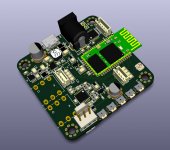
I had some better success with these cheap MP3/FM/TF-Card/BT modules with display. (But even these needed some change in their LC filter)
Like these:
Auto Digital LED 12V Bluetooth MP3 WMA Decoder FM Audio Modul USB TF Radio H293 | eBay
But they're avail cheaper. (Hard to coat them anyway.)
Best would be a board with CSR chipset, like one i have actually in the pipeline.
(Or using a isolated DCDC for the BT)
Attachments
Last edited:
No I was referring to the DC converter with LCD screen, not the Bluetooth module. I will go for what you all recommended as I am just knowledgeable to be dangerous! I suppose you hook up your fully charged batteries to the converter then use a multimeter to dial in the output voltage? Right? The Bluetooth module is just a PCB without display. I used one of the FM/am/ USB/micro SD/ Bluetooth 4.0 boards on my son's boat speakers and had a hell of a time sealing all the thru holes in the face of the board! So mine will be internally mounted to keep out water better?
On mine, I have noise whether I run off of a switcher or straight from lithium cells. The on board voltage scopes out at a fairly clean 5V either way thanks to that 78m05 on board.
I have that exact board you posted, what did you have to do to get the output quiet?
I also have one of these newer versions with microphone input, same noise problem. If I could fix the interference issue, I really like the board, because it does basically all of your input switching.
Ape FLAC WAV WMA MP3 Decoder 12V Bluetooth Receiver USB Sound Card FM Radio | eBay
I have that exact board you posted, what did you have to do to get the output quiet?
Which one?
Just 35V.
--------------
Beside that, having a bt receiver hanging on a buck, always gave me trouble with noise. (Those cheap BT implementations even have some noise when powered by pure DC, when not made by CSR and connected differentially to the amp.)
I had some better success with these cheap MP3/FM/TF-Card/BT modules with display. (But even these needed some change in their LC filter)
Like these:
Auto Digital LED 12V Bluetooth MP3 WMA Decoder FM Audio Modul USB TF Radio H293 | eBay
But they're avail cheaper. (Hard to coat them anyway.)
Best would be a board with CSR chipset, like one i have actually in the pipeline.
(Or using a isolated DCDC for the BT)
Nice board Doc!
Before cheap integrated amps with BT were available I made a few with a BT module and class D amp separately. Always had noise issue and only thing that fixed it was a Murata isolated DC-DC converter.
That Sanwu I have now makes it easy. Also no noise.
No I was referring to the DC converter with LCD screen, not the Bluetooth module. I will go for what you all recommended as I am just knowledgeable to be dangerous! I suppose you hook up your fully charged batteries to the converter then use a multimeter to dial in the output voltage? Right? The Bluetooth module is just a PCB without display. I used one of the FM/am/ USB/micro SD/ Bluetooth 4.0 boards on my son's boat speakers and had a hell of a time sealing all the thru holes in the face of the board! So mine will be internally mounted to keep out water better?
Ah, those DC-DC are actually OK, they are intended for you to make a DIY lab supply out of a PC power supply type of deal. You are correct that you would hook up your batteries to the input of the DC-DC, then dial in the output voltage with a multimeter, then hook up your amps.
If you want to ensure the output never changes, dial in the output voltage, de-solder the adjustment pot, measure it, then solder in a fixed resistor divider. You could also just put some glue/RTV on the adjustment screw once its set, and that will probably be fine.
Then just turn the current up to maximum, and set your undervoltage cutoff to around 20V to avoid totally killing the batteries if there is not much sun out.
Which BT board did you go with? Have you tried it out yet? Curious if it has interference out of the box.
Which one?
This one here
Auto Digital LED 12V Bluetooth MP3 WMA Decoder FM Audio Modul USB TF Radio H293 | eBay
Last edited:
- Home
- Amplifiers
- Class D
- Cheap TPA3118D2 boards, modding them and everything that comes with it