More Farads, Bigger Bass from 3118D2
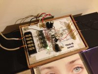
I added a second 470 uF capacitor on the power rails for total of 4 x 470 uF to see if it would improve the sound. On one song where I listened to the bass before then after, there was a noticeable difference in what I thought was just adequate before, now it is much improved. It's the bass on the kick drum that improved - it is now authoritative and controlled. Bass notes from double bass however, still sound the same as I don't think they were lacking before. Anyhow, that was a simple upgrade and well worth it. Here is photo of foam core amp with additional caps. These are Panasonics.
I added a second 470 uF capacitor on the power rails for total of 4 x 470 uF to see if it would improve the sound. On one song where I listened to the bass before then after, there was a noticeable difference in what I thought was just adequate before, now it is much improved. It's the bass on the kick drum that improved - it is now authoritative and controlled. Bass notes from double bass however, still sound the same as I don't think they were lacking before. Anyhow, that was a simple upgrade and well worth it. Here is photo of foam core amp with additional caps. These are Panasonics.
Attachments
As a passing comment, I did read a while ago in the full range forum that some people really liked the Fostex FF85WK.
In any case, if class D amps are not ideal for speakers with crossovers, can anyone name some that are? I read tweeter/woofer combinations are superior than full range drivers for heavy metal, etc.
In any case, if class D amps are not ideal for speakers with crossovers, can anyone name some that are? I read tweeter/woofer combinations are superior than full range drivers for heavy metal, etc.
As a passing comment, I did read a while ago in the full range forum that some people really liked the Fostex FF85WK.
In any case, if class D amps are not ideal for speakers with crossovers, can anyone name some that are? I read tweeter/woofer combinations are superior than full range drivers for heavy metal, etc.
Of course Class D amps are perfectly suited to speakers w/ crossovers. That's what most people are using them for.
I read tweeter/woofer combinations are superior than full range drivers for heavy metal, etc.
I listen to most types of music but metal and especially doom and death metal are my preferred genres. (Hence my profile name which is from the doom metal band Saturnus of which I'm a huge fan).
I certainly have no problem enjoying it with my full-rangers. However, one thing must be said. Good metal recordings that get the most optimum out of any speakers (and amps) are unfortunately relatively rare.
I think my Metallica CD's and all my classic rock bands like Lynnard Skynard, Doors, Led Zep, sound good on my full range driver with FH3i enclosure. I think the reason why people say you need multiways is that if you like it loud to the point of feeling the slam on your chest, you need large area drivers with lots of power for dB. I don't like my music loud so it's not a problem However, very complex classical orchestral pieces seem to overwhelm a single driver and advantage of point source stereo imaging and soundstage do not matter anymore. Class D amps can still drive multiways especially bi-amping with FAST and openbaffle arrangements.
Just as a note to anyone who thinks little TI class D chips are only low power, my latest order of IC's from TI just arrived. I am holding in my hand a 14 x 14 mm x 1.2 mm thick 64 pin quad flat pack chip called the TAS5630B. It makes 300 watts per channel (10% THD), but if you run at *ONLY* 240 watts per channel into 4 ohms you get 1% THD. And if you stay below 100 watts output the THD is less than 0.1%. Pretty amazing and again, I tip my hat to the designers at TI for making such an amazing piece of technology. I think you can drive heavy metal multiway pretty effectively with 300 watts, and certainly for critical listening of classical orchestral pieces on a nice multiway speakers 240 watts should be enough. As a TI class D implementation the efficiency is pretty high. Data sheet shows 11 watts dissipation at 100 watts output into 8 ohms.
Last edited:
this guys done a lot with the 5630's
http://www.diyaudio.com/forums/vend...s-aluminum-case-finished-new-year-coming.html
and theres a few other amateur builds on here.
http://www.diyaudio.com/forums/vend...s-aluminum-case-finished-new-year-coming.html
and theres a few other amateur builds on here.
Not terribly impressed by the TAS5630B which I have heard. It's a good example of last generation TI designs. It's fairly old (in revision C now) and an obvious precursor to the current generation.
Don't get me wrong, it's a fantastic amp chip but not one I feel is better in any way than good TC2000 based amps. Except maybe in bass performance but that has much to do with output coils and input capacitors used.
Don't get me wrong, it's a fantastic amp chip but not one I feel is better in any way than good TC2000 based amps. Except maybe in bass performance but that has much to do with output coils and input capacitors used.
I added a second 470 uF capacitor on the power rails for total of 4 x 470 uF to see if it would improve the sound. On one song where I listened to the bass before then after, there was a noticeable difference in what I thought was just adequate before, now it is much improved. It's the bass on the kick drum that improved - it is now authoritative and controlled. Bass notes from double bass however, still sound the same as I don't think they were lacking before. Anyhow, that was a simple upgrade and well worth it. Here is photo of foam core amp with additional caps. These are Panasonics.
Nice build, probably I will try this chip one day too.
From my experience with Tripath TA2024 amp. 470uf good quality low ESR caps(I use panasonicFM) close near chip is enough.
Then one additional 6800-10 000uf somewhere near, lets say on boards power input terminals. It improve bass performance a lot, compared to just plain 470uf.
Try it with your amp.
Zigis,
Thanks!") I am not sure too many people would say that considering how ugly the dead bug style is. There is something special about it for me though - it is very organic looking and all the wires are just where they need to be and as long as they need to be without making lots of neat looking rectilinear patterns. Plus when you hand make something it will always look good to you - as is the case that no one thinks their own baby is ugly . Appreciate the feedback though.
I am not sure too many people would say that considering how ugly the dead bug style is. There is something special about it for me though - it is very organic looking and all the wires are just where they need to be and as long as they need to be without making lots of neat looking rectilinear patterns. Plus when you hand make something it will always look good to you - as is the case that no one thinks their own baby is ugly . Appreciate the feedback though.
It looks like some big caps in the 6800 uF range will be on my next order to Digikey... I can't say that I would complain about the bass now but then I guess you don't know what you are missing until you hear it. I think they test will be to parallel the full range driver with a bandpass labyrinth ported subwoofer that I have from wife's my old JVC component stereo. If it can still drive that and the full range with oomph that will be an achievement.
Thanks!
I am not sure too many people would say that considering how ugly the dead bug style is. There is something special about it for me though - it is very organic looking and all the wires are just where they need to be and as long as they need to be without making lots of neat looking rectilinear patterns. Plus when you hand make something it will always look good to you - as is the case that no one thinks their own baby is ugly . Appreciate the feedback though.It looks like some big caps in the 6800 uF range will be on my next order to Digikey... I can't say that I would complain about the bass now but then I guess you don't know what you are missing until you hear it. I think they test will be to parallel the full range driver with a bandpass labyrinth ported subwoofer that I have from wife's my old JVC component stereo. If it can still drive that and the full range with oomph that will be an achievement.
Last edited:
Ok, actually I was thinking about PCB, I am not so brave as you (however I use p2p on tubes and chipamps)
For best performance, I believe, 470uf caps and small bypass caps must be as close as possible to chip power legs, with as short wires as possible.
For PCB amp you can't do anything yet. If I make PCB design, I think I could save 1 cm or so between caps and chip.
Wit your p2p amp you can try to move caps bit closer, wire from chip to cap as short as possible, without free loops, maybe solder to cap's leg closer to cap's body. Every millimeter count.
Of course if you don't afraid to damage your fragile construction.
Wen you get large cap, you can solder one leg and other touch/ontouch or use switch on the fly, you clearly can hear large difference, if you even here additional small 470.
(however I use p2p on tubes and chipamps)For best performance, I believe, 470uf caps and small bypass caps must be as close as possible to chip power legs, with as short wires as possible.
For PCB amp you can't do anything yet. If I make PCB design, I think I could save 1 cm or so between caps and chip.
Wit your p2p amp you can try to move caps bit closer, wire from chip to cap as short as possible, without free loops, maybe solder to cap's leg closer to cap's body. Every millimeter count.
Of course if you don't afraid to damage your fragile construction.
Wen you get large cap, you can solder one leg and other touch/ontouch or use switch on the fly, you clearly can hear large difference, if you even here additional small 470.
Ok, actually I was thinking about PCB, I am not so brave as you
For best performance, I believe, 470uf caps and small bypass caps must be as close as possible to chip power legs, with as short wires as possible.
For PCB amp you can't do anything yet. If I make PCB design, I think I could save 1 cm or so between caps and chip.
Wit your p2p amp you can try to move caps bit closer, wire from chip to cap as short as possible, without free loops, maybe solder to cap's leg closer to cap's body. Every millimeter count.
Of course if you don't afraid to damage your fragile construction.
Wen you get large cap, you can solder one leg and other touch/ontouch or use switch on the fly, you clearly can hear large difference, if you even here additional small 470.
I have two different bypass caps (1000 pF 50 V and 0.1 uF 50 V) on the power leads to the chip and they are only 5 mm away with the 470 uF about 20 to 30 mm away. I have absolutely no noise on the system that you can hear (have to put ear within 2 inches of drivers to hear soft hiss when no music is playing). I think the bypass and aluminum foil groundplane are doing their job. Interestingly, the nicely made PCB version with a nice groundplane isn't any quieter than the foam and foil p2p construction.
That's a good tip to try putting a switch on the leg of the additional cap to do an A/B test of sound with and without the capacitor. I'll try that...
Regards,
X
Mr X.
I do not see any bulk ecap in your ckt, in my TPA3100D2 design, I am using a Nichicon (4700uF/35V), (could be bigger, I used a 18mm Diam can!!) for a bulk ecap and local to each channel, 2 of Silmic2, (220uF/35V).
This amp, I have driving the Dynaudio Gemini spkrs, which are spec'd as 4 ohm. It sounds great, as a comparison I test against my Pioneer SX-950.
To step it up a notch it could use a sub however.
There are limits to your bug implementation, because you can not put the comps as close as one can do on a PCB and have lots of copper between them for a low impedance connections..
None the less good job, now you understand the limits of this method.
The next class "D" amp that I make will be similar as shown in figure 27 of the TPA3116/18/30 DS.
Cheers Rick
Rsavas,
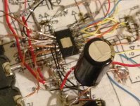
Not sure why you don't see bulk caps in my circuit. The photo (post #182) clearly shows four Panasonic 470 uF caps on the ends of IC. Two are lying flat on board and two are standing up straight. Even with dead bug, I managed to get the small SMD bypass caps quite close. The wire is rather small 22 gage used for the power connections to the leads on the IC but I put the bypass caps within mm of the IC lead. Here a closeup photo showing how the two bypass caps are directly soldered onto the 22 gage main power lead from the IC pin and is located about 5 mm away.
Not sure why you don't see bulk caps in my circuit. The photo (post #182) clearly shows four Panasonic 470 uF caps on the ends of IC. Two are lying flat on board and two are standing up straight. Even with dead bug, I managed to get the small SMD bypass caps quite close. The wire is rather small 22 gage used for the power connections to the leads on the IC but I put the bypass caps within mm of the IC lead. Here a closeup photo showing how the two bypass caps are directly soldered onto the 22 gage main power lead from the IC pin and is located about 5 mm away.
Attachments
Last edited:
not enough capacity
22awg is pretty small but it is a short distance.
Yes, myself and others are saying that this is not enough capacity, I am using a total of (4700u+(2x220u))=5140uF, which seems to fine from what I can tell, so far and I am not running a subw.Not sure why you don't see bulk caps in my circuit. The photo (post #182) clearly shows four Panasonic 470 uF caps on the ends of IC
22awg is pretty small but it is a short distance.
Klipsch La Scalas
Agreed! Class D sounds terrific with my La Scalas equipped with A.L.K. crossovers!
I've always been impressed with how quick, yet huge these speakers sound.
They're like Jackie Gleason. Huge, but they can move!
Mark
Of course Class D amps are perfectly suited to speakers w/ crossovers. That's what most people are using them for.
Agreed! Class D sounds terrific with my La Scalas equipped with A.L.K. crossovers!
I've always been impressed with how quick, yet huge these speakers sound.
They're like Jackie Gleason. Huge, but they can move!
Mark
Know, I did not specifically say what size ecap will make an audible diff, but logic says that the larger the better, up to a point that is, I think this is the largest one would need to go, so that is why I chose this value.So you are saying circa 5000 uF will make an audible difference? Wow, that is a huge increase over factory recommended 220 uF.
Is there a way to calculate what the capacitance should be to prevent power supply rail sag?
The TI demo board probably used a lab supply, so that is no judge of the final application supply.
Since I have a external supply, I have to make it this big since it could be hooked up to DC rectifier/transformer with who knows what they have for a bulk decoup ecap.
If I was to use a regular transformer, this would be the size I chose.
Calculating the ripple, is available on the web & in this vary forum, but it is rather empirical.
Note, this chip has a 70dB PSRR, so that is something to note.
I have built/heard a few stereo's in my day, I am surprised at the absolute zero ac line hum through my application, noise is very low as well. I have tons of hi-freq clocks running as well. It is on a 4-layer pcb, as this is imperative for a low noise supply.
I am almost certain that many new TV/Stereos use these parts.
What is your power supply arrangement?
Last edited:
- Home
- Amplifiers
- Class D
- Cheap TPA3118D2 boards, modding them and everything that comes with it