e conveniently passed to a sub. Of course, the ultimate end of this process is a true infinite baffle -- a speaker mounted in a wall with an empty room behind it.
A speaker mounted flush on a wall doesn't have the nice deep soundstage of a speaker sitting say 4 ft from a wall. I think the Nautaloss speaker achieves an approximation of an IB in that there are no back reflections to color the sound from the cone and it also doesn't have the dips of the wide OB while allowing you to place it away from wall for good soundstage and imaging.
fractional size K ?
Hi there X: How do you apply the fraction multiplier (such as 0.53x) to the Karlson enclosure? (0.53)x(volume) or (0.53)x(dimensions)? ...regards, Michael
Bojonjovi,
For a desktop speaker that is a manageable size and sounds good I recommend the 0.4x mini Karlsonator with a single Vifa TC9FD. It is 12 in tall x 6.25 in wide and gets about 75 Hz bass extension.
http://www.diyaudio.com/forums/full-range/239338-mini-karlsonator-0-53x-dual-tc9fds.html
Hi there X: How do you apply the fraction multiplier (such as 0.53x) to the Karlson enclosure? (0.53)x(volume) or (0.53)x(dimensions)? ...regards, Michael
MNS, to me your latest measurements look just fine. You can use them, just change gating and smoothing.
The key is how to read those measurements. I warmly recommend that you download Rudolf's paper and study it before going further. His web pages are in German but easy to read with pictures (use Google translate?)You are facing the physical limits of single driver dipole, it is just that. I was in similar situation a year ago... We must accept the fact that dipole operation (radiation) happens only in a limited band for a single driver/baffle size- and most of that band has 6dB/octave roll-off that must be equalized.
The key is how to read those measurements. I warmly recommend that you download Rudolf's paper and study it before going further. His web pages are in German but easy to read with pictures (use Google translate?)You are facing the physical limits of single driver dipole, it is just that. I was in similar situation a year ago... We must accept the fact that dipole operation (radiation) happens only in a limited band for a single driver/baffle size- and most of that band has 6dB/octave roll-off that must be equalized.
Last edited:
Thanks for the links ")
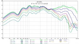
Have currently done 5 sets of measures and polar plots... Looking at the data so far, its easy to tell that as the cut-out increases in size, the better the polar response becomes. =>8000Hz look to be unaffected by the cut-out size.
May be worth doing a few plots just for 4K, 5K, 6K, 7K and 8K range
As Juhazi said above, and it's been said earlier by Rudolf. The moment you make a cut-out in the [main] baffle. The bottom end roll-off becomes a product of the [now inner] baffle... for this 20" x 38" baffle with an inner 14cm x 21cm baffle, roll off starts at about 1000Hz. 500Hz looks bad on the measures I've done as it looks to be the centre of a null.
Paul
Yep, so far with a single driver... the width of the inner baffle [14cm] controls the bass extension and the point at which the driver starts to beam [along with the driver itself]. Increasing the cut-out's width creates a tidier dipole radiation pattern from ~500Hz to ~4K region... the first few cuts 2", 2.5" and 3" seeing the biggest changes, with 3.5", 4" and 4.5" less so. 4" and 4.5" measures are near identical.
There are two dips, first at ~520Hz the second ~830Hz, so a 1000Hz XO might be the safe bet. Or, a second driver [1.5 config] and EQ... The second [.5] driver would need the same baffle width to keep the dipole pattern, or there's no point doing the cut out [yes/no!?]
Three cuts and measures left to do, 5", 5.5" and 6"... at six inches, there will just be a 1" frame, very much like the outer frame on the NaO Note II series.
Paul
Just for comparison I add the horizontal 0-90° measurements (10° steps) for my 21x14 cm baffle as shown in post #30

That is about the same size as the inner baffle of BMS, but no outer "frame/baffle" to speak of. The first (and only) dipole notch is at 4 kHz. The curves should be "valid" down to 1 kHz. I'm really curious how they will compare to your cut outs.
That is about the same size as the inner baffle of BMS, but no outer "frame/baffle" to speak of. The first (and only) dipole notch is at 4 kHz. The curves should be "valid" down to 1 kHz. I'm really curious how they will compare to your cut outs.
Rudolf, what you've shown is the same as how the 21cm x 14cm baffle simulates in Basta... The on-axis response curve I'm getting follows the same line but with dips at ~500Hz and ~830Hz... perhaps the outer section of the larger baffle is causing this problem... have noted that as the width of material at the outer edged reduces, the response around the two dips get better.
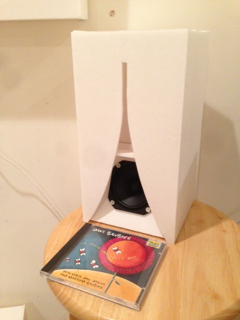
included measure from last set done for 4.5" cut-out around the 21x14 inner baffle. Still having problems with an early reflection, but 0 to 70 are all good enough... Gated and 1/6 smoothing.
included measure from last set done for 4.5" cut-out around the 21x14 inner baffle. Still having problems with an early reflection, but 0 to 70 are all good enough... Gated and 1/6 smoothing.
Attachments
Last edited:
Hmm... been reading trough the latter posts within the MA driver measurements thread, specifically Bob's comment about Troels' treatise on microphone mounting. Which I've now had the time to Google.
Two points to raise... First, I've surface mounted the driver, not flush mounted it. Second, I'm using a bulky camera tripod & head with the microphone sat atop. From Troels' writing, both these things will cause some bad mojo in the measurements.
Making a new test baffle and getting a slim rod to move the mic' away from the tripod wont cost much & might be worth trying out just in-case. Can also get some MDF to make a 50cm x 50cm test OB for the A7.3
|-O-|
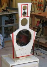
Had a stupid idea ... Would like to do a FR & 8" woofer with a baffle shape the same as the LX521 and either a single Alpha 15A in an angled H-frame [think N-shape] or duel Alpha 15A slot loaded...
Two points to raise... First, I've surface mounted the driver, not flush mounted it. Second, I'm using a bulky camera tripod & head with the microphone sat atop. From Troels' writing, both these things will cause some bad mojo in the measurements.
Making a new test baffle and getting a slim rod to move the mic' away from the tripod wont cost much & might be worth trying out just in-case. Can also get some MDF to make a 50cm x 50cm test OB for the A7.3
|-O-|
Had a stupid idea ... Would like to do a FR & 8" woofer with a baffle shape the same as the LX521 and either a single Alpha 15A in an angled H-frame [think N-shape] or duel Alpha 15A slot loaded...
I simulated the floor reflection for a driver at 90 cm height, measured from 1 m distance:The on-axis response curve I'm getting follows the same line but with dips at ~500Hz and ~830Hz... perhaps the outer section of the larger baffle is causing this problem...

It looks suspiciously like your dips at 500 and 800 Hz.
BTW: It can't be the outer section of the larger baffle, because your dip doesn't change its frequency with changing angle.Surface mounting of a driver is essential for dome tweeters with their ubiquitious ~10 cm circular baffles. It is less important for cone FR drivers and drivers with non-circular baskets.Two points to raise... First, I've surface mounted the driver, not flush mounted it. Second, I'm using a bulky camera tripod & head with the microphone sat atop. From Troels' writing, both these things will cause some bad mojo in the measurements.
It does not make a world of a difference, but if you have the material already, it's worth the effort.... getting a slim rod to move the mic' away from the tripod wont cost much & might be worth trying out just in-case.
A stupid idea indeed ...Would like to do a FR & 8" woofer with a baffle shape the same as the LX521...
Yes, the simulated floor reflection does look suspiciously familiar.
Currently trying a slimmer microphone mount [a 1m ruler] and it makes a very small difference in the measure, <1dB magnitude... but if it helps getting a cleaner reading
Same baffle as the LX521, with some adjustment for the drivers used
Currently trying a slimmer microphone mount [a 1m ruler] and it makes a very small difference in the measure, <1dB magnitude... but if it helps getting a cleaner reading
Same baffle as the LX521, with some adjustment for the drivers used
@Rudolf:
@BMS:
I think all this hyper vigilance to "proper" mic techniques is really only for HF stuff for dome tweeters and the like as Rudolf pointed out. For most folks dealing with a full range drivers, and especially ones with non-circular baskets (like the TC9FD), these precautions don't really change the measurement more than 1 dB as BMS found out.
When measurements using so-called "poor practices" yield frequency response discrepancies of 10 to 15 dB magnitude, blaming measurement protocol is probably unwarranted.
Surface mounting of a driver is essential for dome tweeters with their ubiquitious ~10 cm circular baffles. It is less important for cone FR drivers and drivers with non-circular baskets.
@BMS:
it makes a very small difference in the measure, <1dB magnitude.
I think all this hyper vigilance to "proper" mic techniques is really only for HF stuff for dome tweeters and the like as Rudolf pointed out. For most folks dealing with a full range drivers, and especially ones with non-circular baskets (like the TC9FD), these precautions don't really change the measurement more than 1 dB as BMS found out.
When measurements using so-called "poor practices" yield frequency response discrepancies of 10 to 15 dB magnitude, blaming measurement protocol is probably unwarranted.
The LX521 is a baffle "with some adjustment for the drivers used". The basic baffle according to basis theory would have been something like this (red outline):Same baffle as the LX521, with some adjustment for the drivers used
If one uses different drivers and different Xovers from SL's, why would one start from his "changed" baffle? Mercedes didn't start into the new F1 season with its cars painted in Red Bull colors, although those apparently were the "winning" colors ... didn't they.
Attachments
Rudolf, your being a very patient man, thank you... Like normal, I made light of something quite complicated. I've been trying to use Basta to run baffle simulations with a selection of drivers I'm looking to use. The basic baffle shape starts out very much like the outline you've drawn. No tweeters though Just had a coffee shot and am about to start reading through Google translated pages of the dipol+ site.
Intrigued how you simulated the floor reflection with the EDGE software.
Particularly off-axis, free space around the driver has had biggest impact on the measures done so far. Early reflections killing the usefulness of measures at 70°, 80° and 90°... Slight adjustments to room furniture and attention to 0° alignment, has yielded far better off-axis measurements. Thing is, I can't take the room out of the speaker response, without taking the speaker out of the room... So stuck with the dips unfortunately
Just had a coffee shot and am about to start reading through Google translated pages of the dipol+ site.Intrigued how you simulated the floor reflection with the EDGE software.
Particularly off-axis, free space around the driver has had biggest impact on the measures done so far. Early reflections killing the usefulness of measures at 70°, 80° and 90°... Slight adjustments to room furniture and attention to 0° alignment, has yielded far better off-axis measurements. Thing is, I can't take the room out of the speaker response, without taking the speaker out of the room... So stuck with the dips unfortunately
Last edited:
AkAbak does floor bounce or ceiling bounce but not both. It assumes infinite ceiling height if you are doing floor bounce and vice versa. Back wall is there too. For corner placement flor and two walls are included but not ceiling. It makes a big impact on speaker response in the 100 to 300 Hz range and one of the reasons REW is so popular.
The floor bounce is simulated by duplicating the loudspeaker mirrored below the floor (Boden) - like this:Intrigued how you simulated the floor reflection with the EDGE software.
In EDGE it looks like this:

Mic stays at the height of the upper driver.
The more I learned about measurements, the less I raved about "slick" diagrams. I wasn't criticising those dips at all. Just tried to find out, what was causing them. When I know what is the cause of a peak or dip, I can estimate if I have to take care of it or not. If it doesn't need attention, it may stay in the diagrams until doomsdayThing is, I can't take the room out of the speaker response, without taking the speaker out of the room... So stuck with the dips unfortunately
You could verify my floor bounce theory by repeating a measurement at half and double the original mic distance and comparing the changing dip frequency.
Thanks both for the replies
X, from what I've seen of your enclosure sim's, AkAbak appears to be quite an adept tool. Shame I don't have a system capable of running it
Rudolf, I'd just got to the picture you've posted on your site before I called back here... Seeing the speaker reflection made things snap into place.
With the correct microphone height [0.87m], the simulated floor reflection is a match for the dips in the measurements. They're not of such a magnitude that it'd cause much of a problem. My sealed woofer has a bad reflection at 250Hz, to get around it I implemented the XO at 250Hz
I'm quite happy that it isn't the way I'm doing the measurements that's causing the problems, more lamenting the fact I don't have a garden to escape into...
BMS,
You need to get a virtual machine for Windows XP. Then you can run it from within Mac, Linux, Win 64 bit, etc.
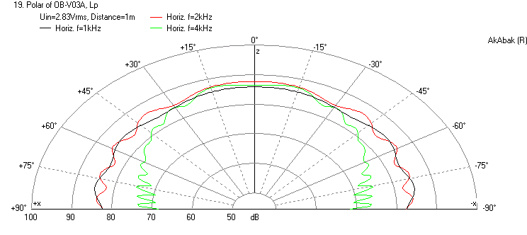
Here is a sim of the 4FE35 in a 21 cm tall x 14 cm wide baffle at 90 cm from the floor and 1.22 m from the back wall. It seems to have the similar characteristic that Rudolf's sim has, although I don't know how a back wall plays into his sim.
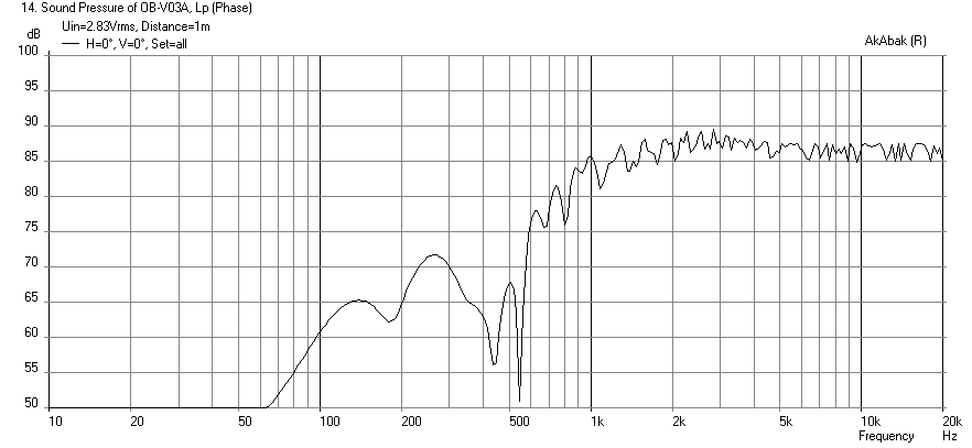
Polar response for 1 kHz, 2 kHz, 4 kHz at 1 m:
You need to get a virtual machine for Windows XP. Then you can run it from within Mac, Linux, Win 64 bit, etc.
Here is a sim of the 4FE35 in a 21 cm tall x 14 cm wide baffle at 90 cm from the floor and 1.22 m from the back wall. It seems to have the similar characteristic that Rudolf's sim has, although I don't know how a back wall plays into his sim.
Polar response for 1 kHz, 2 kHz, 4 kHz at 1 m:
Attachments

Last edited:
- Home
- Loudspeakers
- Full Range
- Cheap and FAST OB, Literally