The device on the right looks like a real TIP14x to me - what brand was it, Philips, ST or something else? If it was Philips, then the date code should have been from the early-90s - they stopped making it after that. But those devices are very good indeed, with solid copper tabs, etc. As long as it stays stable, it's practically indestructible in low-rail (< +/- 30V) applications. If it oscillates, it will go into thermal runaway pretty quickly and self-destruct.
Bone said:Hey burnedfingers its not supposed to be an audiophile amp its a guitar amp so the more distortion the better")
Tony
Very true LMAO.
I use a soft limiter which gives a valve distortion sound without the expense of using valves.
Hello
Here is a very very simple amp using darlington transistor.
Seem to be a working schematic if any would want a very easy first amp, parts value are in the web page.
http://english.cxem.net/amplifier/amplifier19.php
Bye
Gaetan
Here is a very very simple amp using darlington transistor.
Seem to be a working schematic if any would want a very easy first amp, parts value are in the web page.
http://english.cxem.net/amplifier/amplifier19.php
Bye
Gaetan
Attachments
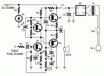
I built that circuit few years ago and I can tell that it is NOT a "working" schematic, at least not in the true meaning of that term. The circuit has issues and will not work properly in the form it is depicted in the schematic. Yes it does amplify and emit sound but it is less than decent in that respect and requires some modifications, mainly to bias circuit, tone control stage and to volume control arrangement. Some compensation against oscillation and an addition of a mains fuse does no harm either. There were some other things that I have already forgotten. This circuit also pretty much suffers from the same issues as the “cheap 150W amp”, although - to be fair - it is, in my opinion, a slightly better design. But no, I can’t recommend anyone to build this amplifier since many better alternatives exist in almost equally simple form. – Not to mention chip amps, which are perfect “simple” projects.
gaetan .....
i am very sorry to say but watching yor posts the latest one year or so i find you extremely easy fooled by schematics like that .....
i ve been involved in scematics like that and most of them was a catastrofy ..... ( consider also that i mostly play on quiet high rail voltage )
but then of course me , you , and many other respected memebers of the forum are probably people with no knowledge or technical skills since the original aythor of this thread "kapibara" prooved all of us wrong and made a working amp with a new pcb stollen from john fishers schematic .....
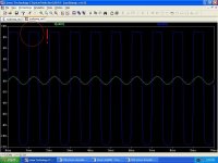
and of course we all waiting kapibara to post performance results and power , frequency figures ..... but nothing ......we only get pictures of nicelly made pcb ....
thats my news
i am very sorry to say but watching yor posts the latest one year or so i find you extremely easy fooled by schematics like that .....
i ve been involved in scematics like that and most of them was a catastrofy ..... ( consider also that i mostly play on quiet high rail voltage )
but then of course me , you , and many other respected memebers of the forum are probably people with no knowledge or technical skills since the original aythor of this thread "kapibara" prooved all of us wrong and made a working amp with a new pcb stollen from john fishers schematic .....
and of course we all waiting kapibara to post performance results and power , frequency figures ..... but nothing ......we only get pictures of nicelly made pcb ....
thats my news
> http://english.cxem.net/amplifier/amplifier19.php
This schematic is workable, at least for some reasonably chosen sets of component values. However, all the voltage gain is obtained from the single VAS transistor, so that needs to have a very high beta, preferably >1000, to be able to obtain enough open loop gain which can be applied to reduce distortion.
I'll simulate and check the distortion numbers later, but it will definitely benefit from an additional PNP gain stage in front of the VAS, and maybe a modified 2nd-order lead compensation schema.
Edit: The suggested ratio of R10 (68k) to R2 (470R) is unrealistic - this gives a closed-loop gain of ~140 (~43 dB), which is too high to realize from a single BJT stage. A more realistic gain from this kind of topology is 30 (~30 dB), for which the value of R2 should be ~2k2.
It is “workable”, as in the sense that it amplifies the signal but does not produce a decent sound. Yes: The VAS should be reasonably fast and have a high beta, but in this kind of design it also must have rather high power dissipation and it’s pretty difficult to find a device that meets all those criteria. BD139 is not really one of them. An additional gain stage would help, or alternatively adding a driver stage in front of the Darlingtons.
BD139 also has too low beta for the bias circuit to work correctly and this circuit will have plenty of crossover distortion due to that. This is the most obvious flaw of the design but does not reveal itself just by looking at the schematic.
Due to less phase shifts this type of circuit is much more stable than the generic topology that has a separate input stage and a VAS, yet I wouldn’t still entirely rely only on compensation shown by the schematic. I would also add a RC Zobel to the output.
The same reason that makes the circuit stable makes it prone to amplify the ripple of the power supply.
The circuit does not tolerate any kind of short circuits. The amp will have an annoying start up “thump”. Pretty much all the basic problems that bother most of the simple discrete designs exist in this one as well.
Since the circuit is inverting the volume potentiometer interferes with the amp’s gain. There really should be a buffer that would ensure constant source impedance of the stage feeding the power amp. Yes, the power amp's gain is also unneccessarily high, but it must be that way due to preamp circuit design. Converting to "Hifi" application naturally requires modifications.
Sure, this circuit can be made to work decently with some tedious tweaking and by redesigning some things. I’m pretty sure you can do that to all circuits. But once it works right it’s still just a mediocre amp. The point is; the beginners who build this kind of stuff choose designs like this because they want an easy and simple project and really do not understand all the issues involved. It’s the reason why the cheap 150W amp design and many other similar ones keep coming up again and again in this forum. Some of these beginners do not even understand how the circuit works and therefore expecting them to be able to tweak it is quite much. Some approaches to tweaking / modifying would pretty much mean a complete redesign of the circuit, which is totally out of their reach.
As closing words to this off topic discussion, this design is actually a rip off of two guitar amplifier projects from the 60's - 70's era. The other was the Heatkit TA-17 and the other was the M/M/M Instrument Amplifier featured in Popular Electronics Magazine (designed by Daniel Meyer). I would suggest persons who are interested in this simple amp to find these sources of information instead, as they seem to be planned out better than what their copy is.
Would any body be interested in having a look at an eagle pcb and pic of a perfectly working, although decommissioned, amp? I originally built it the amp on perf board but then finally made a pcb and installed it in a sub with rod elliots active crossover and dropped the voltage down some. Again , i used this amp for about a year with no problem at all except that it was very noisy but that could be due to my design.
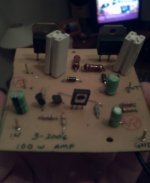
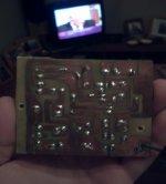
i know what everyone is thinking, ugly ugly!!, but this was the first amp pcb (pretty close to my first ever pcb) i ever made so cut me some slack ha ha ha
This is the same layout that i used in the perf board version and like i said it works and has never given me any probs. its just hisses pretty loud...
This is the same layout that i used in the perf board version and like i said it works and has never given me any probs. its just hisses pretty loud...
- Status
- This old topic is closed. If you want to reopen this topic, contact a moderator using the "Report Post" button.
- Home
- Amplifiers
- Solid State
- Cheap 100 to 150 Watt Amp