So what did I do wrong?
--
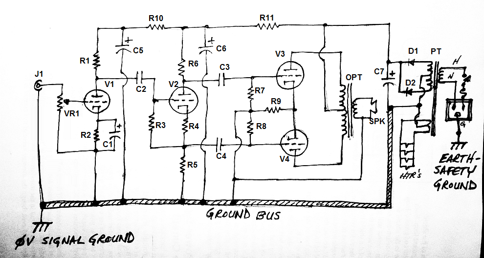
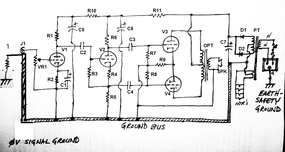
EDIT: I've updated the schematic with parts labels, so it's easier to talk about which parts belong where, etc.
--
I don't think you did anything wrong. It looks basically OK to me. Have you tried it? Does it work? Is it hum free?
Cheers
Ian
I don't think you did anything wrong. It looks basically OK to me. Have you tried it? Does it work? Is it hum free?
Cheers
Ian
I have an amp I need to re-work because of hum. I'm going to try this scheme and see if it fixes it. Hopefully over the next couple of days.
Thanks for the vote of confidence, and Happy New Year!
--
Add a resistor to ground after the pot cursor,
and maybe another one of small value in series with the grid.
The ground area around J1, bottom of Vr1 and bottom of R2 and C2 should be the smallest as possible.
I didn't bother to show details such as grid stoppers, grid leak after the pot wiper, etc. This is all about grounding.
The ground area around J1, bottom of Vr1 and bottom of R2 and C2 should be the smallest as possible.
Do you mean C1, the cathode bypass cap? C2 is the DC-blocking/interstage coupling cap from V1 anode to V2 grid.
Also, I'm not sure what you mean by 'the ground area.' There's a local star ground for that stage in the schematic, which then goes to the ground bus. If that's not what you meant, please explain.
--
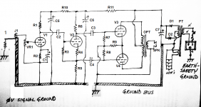
with regards to "loop areas" the gnd of J1 should go to VR1 and the J1/GND bus connection omitted?
I was wondering about that. The way I pictured it, J1 shield might as well be connected straight to the chassis, as long as the ground bus leaves from there. Instead...
I was thinking of putting a 'post' in the chassis, right next to the input stage tube.
- J1 would be insulated from the chassis.
- J1 shield connection wire would go to this post.
- VR1 ground connection would go this post.
- R2 ground would go to this post.
- C1 ground would go to this post.
- Ground Bus wire would leave from this post, back to the rest of the circuit.
--
I didn't bother to show details such as grid stoppers, grid leak after the pot wiper, etc. This is all about grounding.
Do you mean C1, the cathode bypass cap? C2 is the DC-blocking/interstage coupling cap from V1 anode to V2 grid.
Also, I'm not sure what you mean by 'the ground area.' There's a local star ground for that stage in the schematic, which then goes to the ground bus. If that's not what you meant, please explain. --
Any current circulating between
the input socket ground,
the bottom of Vr1, R2, C1,
and the ground bus
will generate a voltage across the impedance of the paths.
As designed, this voltage is amplified.
Connecting the input socket ground and the bottom of Vr1, R2, C1 together sets all these points at the same potential in a kind of local star.
Then this star is then connected to the bus ground
Amplification by V1 will then be much more immune to parasitics induced in the reminding ground path.
A remaining question is where to connect your 0V signal ground.
I should say between the local star and bottom of C5, or less often seen,
but preferably to me, at the non-insulated input socket ground.

Hey Koonw,
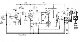
Doesn't the second picture break the rule of only connecting signal ground to chassis at one location? If there is a resistance between the input chassis ground and the output stage chassis ground, there may be a voltage developed.
Why would you break the ground bus and attach the input stage to chassis at one place and the output stage to chassis at a different place?
--
Hi, I've google around on chassis earth and ground for tube amp and seems quite confusing in regards of ground loop.
My understanding is that chassis must always connected to Earth pin of the 240V input (AU standard) no exception.
Please clarify for me the followings:
Should the CT (0V) of 300V-0V-300V secondary be connected to the chassis? (I assume it should be yes)
Should the input (signal ground) also be connected to the chassis? (I believe the answer should be yes)
http://www.diyaudio.com/forums/atta...mm-buzzgroundingproblemsrev1p4danieljoffe.pdfHey Koonw,
Doesn't the second picture break the rule of only connecting signal ground to chassis at one location? If there is a resistance between the input chassis ground and the output stage chassis ground, there may be a voltage developed.
Why would you break the ground bus and attach the input stage to chassis at one place and the output stage to chassis at a different place?
--
http://www.diyaudio.com/forums/tubes-valves/281863-humm-buzz.html
I thought you're on that thread also. Because you're now dividing the amp into 2 parts, considered 2 amp each having it's own ground. And the ground lift only the preamp, not the entire amp, prevent single channel and cross channel loop.
A remaining question is where to connect your 0V signal ground.
I should say between the local star and bottom of C5, or less often seen,
but preferably to me, at the non-insulated input socket ground.
I think I'm following you. Attached is a drawing of what I think you're saying...
--
Attachments
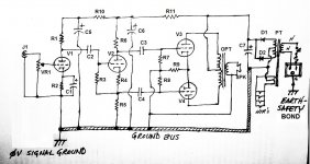
Why tie the heater reference to a point inside a high current loop carrying power supply spikes?
Good question. So, the heater reference should be tied to a point that is outside of any current loops carrying power supply spikes.
Does that mean a good place to tie the heater reference is to its own, separate place on the chassis?
Or should the heater reference be tied to the 'Ground Bus'?
If it does go to the Ground Bus, where along the bus would be best? Wouldn't that risk injecting noise from the AC heaters into the 0V Signal Ground?
(As you can tell, I'm still adrift...)
--
Good question. So, the heater reference should be tied to a point that is outside of any current loops carrying power supply spikes.
Yes, otherwise those spikes are injected into the heater as common mode noise. Tie the reference to the power supply end of the bus. Bypass the heaters for common-mode noise (i.e., a small ceramic cap from each leg to ground).
OK, I've taken some time and read Joffe's paper. I see the reasoning behind using the HBRL and HBRR resistors that ever so slightly elevate the input stages above chassis earth. I also understand Koonw's reasoning for breaking the ground bus into two pieces and grounding the power amp section directly to the Ground Bus (which is directly earthed to chassis).
This particular amp has a single B+ supply but two separate 6.3VCT heater windings. It will take some thinking to arrange everything so that all 'grounds' are going where they should.
BTW, thank you everyone for taking the time to guide me out of my murky incomprehension. This grounding/earthing stuff is pretty subtle.
OK, so here's a drawing that incorporates everything (I think) I've learned so far. Hopefully I'm getting warmer.
--
Attachments
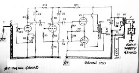
OK, so here's a drawing that incorporates everything (I think) I've learned so far. Hopefully I'm getting warmer.
--
I'm late to the party, so maybe I've missed out on some relevant discussion earlier. But I can't see any possible advantage in splitting the signal ground bus into two separate grounds (driver and output stage) as done in your latest schematic. You might get away without hum, depending on where the two separate chassis connections for the two halves of the ground bus are located, but that would be a matter of luck. I don't see any positive advantage to splitting the ground bus; only possible disadvantages.
I would have thought that what was shown in post 3 was perfectly fine. Signal ground bus connected to chassis through a resistor R1, a capacitor C1, and a shorted bridge rectifier that ensures signal ground can never be more that about 1.5V different from chassis (=safety) ground. I usually go for overkill and use a 35A bridge rectifier for the last item.
Chris
But I can't see any possible advantage in splitting the signal ground bus into two separate grounds (driver and output stage) as done in your latest schematic.
I think that's an artifact, not actually what the drawing was supposed to be. Look at post 53.
That's not an artifact. That's what was proposed by Koonw in post #49 (second picture attachment).
The schematic in post 3 is fine, but it doesn't show the input stage grounding that's been discussed here. It also doesn't show exactly where the heater center tap (return) should be connected. It just gives the chassis ground symbol, and doesn't incorporate SY's recommendations.
I think the justification for the splitting of the two stages' grounds is to provide a ground lift resistor for the input stage ground, per Joffe's article mentioned previously.
I don't know if it's a good idea to have the input stage, output stage and power supply grounds all lifted by a 1R to 10R resistor from chassis earth. I was hoping to get some information on that.
Here's Koonw's modifications showing the Ground Bus lifted by a 1R resistor at the input:
Good idea? Bad idea? (That drawing also does not incorporate SY's heater grounding improvement.)
Is this better? (attached)
--
Attachments
Last edited:
- Status
- This old topic is closed. If you want to reopen this topic, contact a moderator using the "Report Post" button.
- Home
- Amplifiers
- Tubes / Valves
- Chassis earth and ground