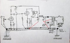
OK, let's see if I'm following correctly. I've done a quick sketch of a two-stage SE amp with the power and output transformers, parts, and where I think everything should be grounded. It would be great if anyone could tell me if this is basically the right idea, or totally off. Thanks.
PS - What I labeled as 'GND POST' is the same as Ian's 'chassis bolt.'
Yup, that's what I do. I have seen other designs where the bus us connected to chassis at the input but that only works it there is just one input (RCA did this a lot on their PA amps in the 1940s and they were very quiet.
Cheers
Ian
Mainly for safety. It also helps provide some screening from external electric fields and reduces coupling caused by internal electric fields.rongon said:OK. If the chassis is not part of the circuit, then why does the signal 0V bus need to be connected to chassis at all?
Note that there are two quite separate things going on here:
1. a metal chassis should be connected to the signal ground to help with screening.
2. a metal chassis should be connected to the incoming mains ground for safety.
People often confuse these two quite different reasons for making connections to the chassis.
This has already been discussed many times.
The old rule, nothing more than a recipe, was :
avoid ground loops, end of the story.
The new rule should be : think
- how and where parasitic voltages are induced in circuits.
- how the signal can be corrupted by circulating currents due to these parasitic voltages in the tracks impedance.
- and finally how to avoid their bad effects .
Since this is a simple circuit you would probably get away with it as drawn, but if you want to get into good habits you should keep the transformer-rectifier-reservoir in a tight loop, then connect the resevoir cap -ve terminal to the bus. Also connect the bus to chassis at the input end, not the noisy end.I've done a quick sketch of a two-stage SE amp with the power and output transformers, parts, and where I think everything should be grounded. It would be great if anyone could tell me if this is basically the right idea, or totally off. Thanks.
Attachments
This has already been discussed many times.
If this has been discussed many times, should we not have a sticky for it? Grounding is a safety issue; thus, probably should have a sticky.
This has already been discussed many times.
If this has been discussed many times, should we not have a sticky for it? Grounding is a safety issue; thus, probably should have a sticky.
Hi Bando,
I am not sure what sticky means.
The lastest discussion on ground connections was there :
http://www.diyaudio.com/forums/anal...preamp-out-signal-grounds-chassis-vs-pcb.html
I am certainly not promoting anything which could present safety issues.
Is all this valid for all equipment including preamps, dacs etc as long as it has a transformer and a metal chassis? What about dc powered equipment with a walwart in a metal chassis?
DC walwart already has adequate protection form mains voltage so you don't need to worry too much about that (which is a main talking point of this whole discussion). However you do still have to follow the same thoughts and design processes to make sure you're not getting ground loops and so forth.
This has already been discussed many times.
The old rule, nothing more than a recipe, was :
avoid ground loops, end of the story.
The new rule should be : think
- how and where parasitic voltages are induced in circuits.
- how the signal can be corrupted by circulating currents due to these parasitic voltages in the tracks impedance.
- and finally how to avoid their bad effects .
Thank you for the general ideas on what to avoid. The question is how to accomplish these goals. I'm afraid I'm still learning how to properly think about these issues.
if you want to get into good habits you should keep the transformer-rectifier-reservoir in a tight loop,
I hope I can get some clarification on this. Do you mean position the power transformer-rectifier-reservoir cap all with their '0V' leads connected to one place, and these parts all located physically as close to each other as possible?
then connect the resevoir cap -ve terminal to the bus.
If I'm using a power transformer HT (plate supply) winding with center tap, the power transformer CT should be connected directly to the negative lead of the reservoir cap, and that should go to the ground bus. Correct?
Also, it's still not clear where the LV (heater supply) winding center tap should be connected. Does this go to the ground bus near where the transformer CT-rectifier-reservoir connects?
Also connect the bus to chassis at the input end, not the noisy end.
OK, that's the opposite of what Ian's saying, but I think I understand.
However, are you saying it's OK to connect the safety ground (green wire) to chassis at the AC inlet, and then have a separate '0V' ground bus connected to chassis at the input end, running back through the amplifier to the transformer-rectifier-reservoir cap 0V lead and heater winding CT?
--
EDIT TO ADD:
Just reading through Chapter 15: Grounding.
It does look like the 'safety-earth bond' can be completely separate from the 'ground bus.' Shown on pg. 271 in the PDF.
I don't know why this wasn't easier for me to see before. I seem to have a block about this... Thanks for the help everyone.
--
Last edited:
However, are you saying it's OK to connect the safety ground (green wire) to chassis at the AC inlet
Never EVER do anything else. Tie that sumbich down as soon as you can.
This pdf shows how to identify the current loops and how to arrange these loops so that they don't interfere with each other.
Okay y'all need to start working on your reading comprehension and looking through the thread. This is the 3rd or 4th time now this particular resource has been referenced.
Just reading through Merlin's Chapter 15: Grounding.
It does look like the 'safety-earth bond' can be completely separate from the 'ground bus.' Shown on pg. 271 in the PDF.
I don't know why this wasn't easier for me to see before. I seem to have a block about this... Thanks for the help everyone.
--
Only one thing has not been specifically addressed. If I'm using AC heaters, where exactly should the (high current and high noise) center tap from the heater winding be connected? To the end of the 'ground bus' with the transformer-rectifier-reservoir?
--
EDIT TO ADD:
Finally, at the very end, there's this:
If the heater supply is not elevated but simply grounded then this connection can
usually be made to any convenient point on the chassis, or else to a point close to the
reservoir capacitor. However, heater hum is induced in many ways so it may be
worth experimenting by making the connection to various points on the circuit
ground to see if any particular place happens to give more favourable hum
performance.
Well, that about raps it up, I think!
--
Last edited:
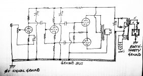
I hope you'll let me try your patience one more time...
Here's a simplified schematic of a push-pull power amp with what I think is a decent grounding scheme. Please let me know if I'm getting warmer.
Thanks.
--
with ref to the valvewizard, if your building a mono amp its good, however if its a stereo (multi-channel) amp post 13 should give better results.
Read and commit to memory that pdf linked in posts 29 & 31.I hope you'll let me try your patience one more time...
Here's a simplified schematic of a push-pull power amp with what I think is a decent grounding scheme. Please let me know if I'm getting warmer.
Thanks.
--
And implement the isolation of current loops. One wire/bus must NOT share currents from two, or more, different loops.
Post13 does not work.
It breaks the basic rule of LOW LOOP AREA.
It's that same rule that Ruff has not got right in his point 4 in post7
The screened cable uses the screen as one half of the close coupled Flow and Return Pair. The screen must stay with the core for the whole Flow and Return Route. It must not be taken as a spearate link that increases the LOOP AREA.
It breaks the basic rule of LOW LOOP AREA.
It's that same rule that Ruff has not got right in his point 4 in post7
For unbalanced inputs (i.e. RCA) use insulated input sockets and connect the screen side to the bus bar at the input stage end.
The screened cable uses the screen as one half of the close coupled Flow and Return Pair. The screen must stay with the core for the whole Flow and Return Route. It must not be taken as a spearate link that increases the LOOP AREA.
Last edited:
Post13 does not work.
It breaks the basic rule of LOW LOOP AREA.
It's that same rule that Ruff has not got right in his point 4 in post7
The screened cable uses the screen as one half of the close coupled Flow and Return Pair. The screen must stay with the core for the whole Flow and Return Route. It must not be taken as a separate link that increases the LOOP AREA.
Who said anything about it being taken as a separate link?? The signal and screen terminate on the free RCA connector which plugs into the RCA socket on the chassis. The RCA socket is isolated from the chassis. A screened cable goes from this connector to the grid of the first tube and its screen goes to the bus close to the input tube.
I think you are suggesting the RCA socket is connected direct to the chassis and there is no connection of the screen to the bus. This is bad news because all the interference currents flowing in the chassis are now common mode at the input.
It would be helpful if, instead of keep repeating the mantra, you actually explained in practical terms what it means.
Cheers
Ian
Read and commit to memory that pdf linked in posts 29 & 31.
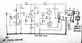
I practically copied an illustration from Chapter 15 - Grounding (the pdf linked in posts 29 & 31).
I printed the pdf out and read it through. Then I tried to make use of what I'd just read. That resulted in the drawing I posted.
Can I ask you to show where I've gone wrong?
And implement the isolation of current loops. One wire/bus must NOT share currents from two, or more, different loops.
That is exactly the part I am not getting.
I kept the current loop created by the pwr transformer-rectifiers-reservoir cap very short and contained. (PT, C7, D1, D2) Its 'ground' joins the 0V bus in one place only.
The current loop formed by the push-pull output stage is contained next (V3, V4, R7, R8, R9, OPT, SPK), since that is the audio gain stage with the highest operating current. Its ground gets connected to the 0V bus next.
The split-load phase splitter is the next stage. (V2, R3, R4, R5, R6, C6) It connects at one point on the 0V bus. (Perhaps I should have made C6 -ve connect to exactly the same point as the grounded end of
R5?)
The input stage (V1, VR1, R1, R2, C1, C5) ground connects to the 0V bus right after the input. (Perhaps I should have connected the -ve end of C5 to the grounded ends of C1, R2 and VR1?)
The input jack is the one and only place where the 0V bus is attached to the chassis.
So what did I do wrong?
--
EDIT: I've updated the schematic with parts labels, so it's easier to talk about which parts belong where, etc.
--
Attachments
Last edited:
- Status
- This old topic is closed. If you want to reopen this topic, contact a moderator using the "Report Post" button.
- Home
- Amplifiers
- Tubes / Valves
- Chassis earth and ground