AKSA said:Forr,
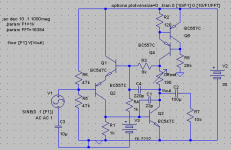
Very interesting sim - could you please post a schemat, I am having some difficulty figuring out what your circuit is!!
Thanks,
Hugh
Hi Hugh
Here there are.
For some new ideas, see here :
http://www.diyaudio.com/forums/showthread.php?postid=1863457#post1863457
Attachments
Hi Sebastien,
Many thanks - I understand clearly.
Question: What is the principal harmonic of the NTP?
I ask this because as it's a single ended series circuit I suspect that it is H2 in the NTP (good name!), and this is quite benign.
If so, what is the profile of this distortion? I would suspect it is monotonically decreasing.....
Cheers,
Hugh
Hi Hugh
---Question: What is the principal harmonic of the NTP?
I ask this because as it's a single ended series circuit I suspect that it is H2 in the NTP (good name!), and this is quite benign.
If so, what is the profile of this distortion? I would suspect it is monotonically decreasing.....---
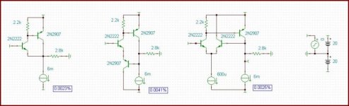
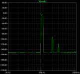
The sims results are quite surprising !
Not those you or me were thinking of for H2 and H3.
CFP
Fourier coefficients
k Amplitude (C) Phase (ø)
0. 615.77m 180
1. 9.99 -90
2. 117.78u 178.3
3. 179.47u -89.08
4. 76.86u -125.53m
5. 39.68u 89.67
6. 21.08u -179.58
7. 11.99u -86.66
Rush + EC
Fourier coefficients
k Amplitude (C) Phase (ø)
0. 1.22 180
1. 9.99 -90
2. 203.25u 178.18
3. 318.25u -89.01
4. 141.18u -68.4m
5. 72.05u 89.7
6. 37.35u -179.45
7. 21.09u -86.31
With a diff input, like the circuit at the right but with a current mirror, disto is 0.00125 %
Fourier coefficients
k Amplitude (C) Phase (ø)
0. 2.4m 180
1. 9.99 -90
2. 125.64u 1.79
3. 26.42u -85.64
4. 1.78u -9.57
5. 814.78n 89.35
6. 205.69n -170.64
7. 351.86n -18.17
---Question: What is the principal harmonic of the NTP?
I ask this because as it's a single ended series circuit I suspect that it is H2 in the NTP (good name!), and this is quite benign.
If so, what is the profile of this distortion? I would suspect it is monotonically decreasing.....---
The sims results are quite surprising !
Not those you or me were thinking of for H2 and H3.
CFP
Fourier coefficients
k Amplitude (C) Phase (ø)
0. 615.77m 180
1. 9.99 -90
2. 117.78u 178.3
3. 179.47u -89.08
4. 76.86u -125.53m
5. 39.68u 89.67
6. 21.08u -179.58
7. 11.99u -86.66
Rush + EC
Fourier coefficients
k Amplitude (C) Phase (ø)
0. 1.22 180
1. 9.99 -90
2. 203.25u 178.18
3. 318.25u -89.01
4. 141.18u -68.4m
5. 72.05u 89.7
6. 37.35u -179.45
7. 21.09u -86.31
With a diff input, like the circuit at the right but with a current mirror, disto is 0.00125 %
Fourier coefficients
k Amplitude (C) Phase (ø)
0. 2.4m 180
1. 9.99 -90
2. 125.64u 1.79
3. 26.42u -85.64
4. 1.78u -9.57
5. 814.78n 89.35
6. 205.69n -170.64
7. 351.86n -18.17
Forr,
My circuit was not intended to be used without gain. If you're not going to use gain, then the CFP is far better. For this reason, these simulation results are not useful in determining the advantages of the circuit I proposed (even though they point out an important fact). (The title of this thread was 'CFP gain stage')
My circuit works much better than the standard CFP as a gain stage because the distorted bias current through R3 is mostly drained away through the PNP Rush transistor.
It looks to me that making distorted amplifiers is somewhat of a trend, so if I ever wanted to experiment with this, I would try using an NTP rather than LTP to get a better spectrum.
Also, if the NTP is faster, it should be better at canceling HF harmonics. Simulation has confirmed this for me - When I use the NTP I don't see as much 4th, 5th, 6th, 7th, etc...
- keantoken
keantoken said:Forr,
My circuit works much better than the standard CFP as a gain stage because the distorted bias current through R3 is mostly drained away through the PNP Rush transistor.
- keantoken
This only works well when used as a gain stage because the bias current serves to distort the operation of the feedback network. There is probably no reason to even think about using it without gain in place of the CFP because it will be slower and more prone to make your circuit oscillate.
I hope this clarifies everything,
- keantoken
Despite my somewhat negative comments about the Rush circuit, I would like to draw attention to the fact that it has been used in one of the more linear amplifying cell I am aware of.
It was patented by Gerard Perrot but here is a variant by Kevin Aylward.
http://www.kevinaylward.co.uk/ee/micampdesign/ComplementaryCurrentSourcedCascodeMicAmp.GIF
This cell does not need to belong to a differential stage.
Looks much like a CFP in a cascode configuration but it is not.
Here the input transistor Q4 (or Q3) is loaded by a CCS and the following stage is a Rush circuit, the DC bias of the common base output transistor Q5 (or Q6) is referenced to the emitter of Q4.
(in Perrot's circuit, the bias is referenced to the LTP point as in many amplifiers using cascode input stages).
So the input transistor sees only very low current variations, thanks to the emitter follower Q2 (or Q1) and very low voltage variations, hence very low power variations.
forr said:Despite my somewhat negative comments about the Rush circuit, I would like to draw attention to the fact that it has been used in one of the more linear amplifying cell I am aware of.
It was patented by Gerard Perrot but here is a variant by Kevin Aylward.
This was a lot like the input stage on a Fairchild in-amp circa 1974. The paper is in the old IEEE collection book, my copy has been stolen. Since it would have used lateral pnp's the performance must have been limited, unfortunatley I can't check the details.
Keantoken,
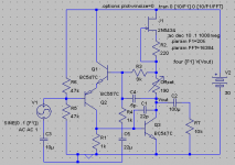
The Rush Cascode makes a very simple gain stage to follow an Opamp so that higher that the normal +-15 voltage can be achieved.
The attached concept drawing shows one such method.
Note the following:
- Very few parts are required.
- The few components produce only small amounts of phase shift at high frequencies, and this makes it easier to keep the feedback stable.
- The opamp produces the necessary bias offset (for Q1 in the circuit)
- Run sufficient current through the Rush Cascode (ie Q1 and Q2) to ensure that the signal current doesn't vary the bias current too much.
- Use a resistor between Q1 and Q2 (ie Re) to vary its gain.
- This circuit is quite low in THD, and the second harmonic is dominant.
- The opamp will be forced into an output bias of +1 to +2 volts typically, and this moves the opamp out of its crossover region, hence forcing it to run in a Class A mode (which is good!).
The attached circuit could form the basis of a simple amplifier, just add your favourite output stage (eg: Allison biased Class A or Krill etc etc).
Paul Bysouth, June 2009
Attachments
Thank you for the idea, Paul.
I have been looking for something like this so that I can power one of my Allison stages with an Opamp (this can make cheap but great audio amp, theoretically).
The Rush cascode can be used as a VAS in place of a single transistor VAS. In simulation, the Rush cascode VAS actually had insignificantly lower distortion than a single VAS transistor. (might be significant if your amp already has .0005% THD)
Paul:
The one thing that concerns me about this circuit is that it doesn't have inherently low output impedance and that correction of output impedance has to go through the whole NFB loop, being affected by the related phase shifts, etc. This is because the output is taken only from collectors; there are no current amplifiers in the output. This concerns me because the Allison does not have linear input impedance, and the harmonics generated by it might be beyond the range of a common audio opamp. I will have to experiment in the simulator.
- keantoken
Hi everyone.
Since the original design is somewhat unrefined and difficult to use, I'm posting this version which should be nearly universal. It performs as well or better than the original. Unfortunately, it's not so much a CFP anymore, with the capacitors.
It works with very low distortion and good spectrum into a 10k load (typical amplifier) at 1V pk-pk output, but to go beyond that and have the same performance takes some more modification. It can be used without an output cap, though output voltage will wander with temperature (this could be a problem). If it's used without an output cap, the offset resistor should be adjusted for 0V output. If no output cap, the offset resistor can be omitted.
This should work at most supply voltages (assuming the transistors are within their limits - if the Jfet is too low voltage, add a resistor in series with it to drop the voltage).
If you build this, please let us know how it sounds.
It currently has a gain of 10, determined by R3 and R4, but made approximate by the Offset resistor.
- keantoken
Attachments
Hi everyone.
Since the original design is somewhat unrefined and difficult to use, I'm posting this version which should be nearly universal. It performs as well or better than the original. Unfortunately, it's not so much a CFP anymore, with the capacitors.
- keantoken
Hi
I have your email.
Can I use a bjt transistor ccs or just a resistor to replace J1 ?
And how about a 20R resistor between Q1 and Q2 emiter ?
Thanx a lot
Paul
Last edited:
Hi
I have your email.
Can I use a bjt transistor ccs or just a resistor to replace J1 ?
And how about a 20R resistor between Q1 and Q2 emiter ?
Thanx a lot
Paul
A 20R resistor will improve stability, Hugh has suggested this. I don't know if it's necessary in real life, but my simulations work well without it.
You can use any CCS. A BJT CCS should improve THD slightly, but I don't know about the spectrum. It might improve THD20 because of lower parasitic capacitance. I wouldn't use a resistor because that adds a lot more loading, which is sure to increase distortion.
- keantoken
That type of CCS only works with Jfets, not BJTs.
More like this.
I'm sorry, I made a mistake when I said a BJT CCS would only improve THD slightly. THD was improved a LOT.
- keantoken
Hi
Why did you raise C4 from 5p to 220p ?
C4 look like a phase lead capacitor.
I've see that you also replaced C5 by a 3 volt source.
Thanx
Paul
Last edited:
Hi
Why did you raise C4 from 5p to 220p ?
C4 look like a phase lead capacitor.
Thanx
Paul
That was an experiment. It drops gain to 0 above audio frequencies, so that I'm not amplifying EMI along with the audio, which may interfere with other equipment. This circuit is fast, so it's capable of amplifying RF. I'm not sure if using C4 for more than phase lead is advisable, but I don't see that it could hurt anything.
I replaced C5 with a battery to get around a simulator problem. It should still actually be a 22uF capacitor.
- keanytoken
Hi
Maby keeping C4 at 5p to keep the circuit high slew rate but adding an input filter to cut rf.
Thanx
Paul
- Status
- This old topic is closed. If you want to reopen this topic, contact a moderator using the "Report Post" button.
- Home
- Amplifiers
- Solid State
- CFP gain stage, modifications.