Hi Andriy,
The circuit is prepared for you to any further analizations!")
Changes:
I am not familiar with this design so I cant go any further right now but I hope it will be a good base for you to continue!
Good luck!
The circuit is prepared for you to any further analizations!
Changes:
- the zeners have now real models for both 4.7V and 15V
- the LED has a custom model where you can adjust the forward voltage based on your real ones
(just right click on that long black text down under
and change the "N" value, now its 3.2V but it depends on your actual LED type) - I added a transient 1msec simulation I like to check even the DC conditions like so:
run the sim with the running man and click to the node where ever you like to measure the voltage
(by default related to GND but with a right click you can choose any node as reference)
and also the currents clicking on the component itself - power supply-s are tied to GND
- values given with short names
I am not familiar with this design so I cant go any further right now but I hope it will be a good base for you to continue!
Good luck!
Attachments
And here is a working one with a sine source and fed back from the IPS output.
Of course it's not ideal this way because of the high feedback currents drawn from the VAS, but it's working.
To get it working I had to increase the R6/7 resistors to 400R but this
is because the default LT transistors have high Vbe arounf 800mV...
Also you can draw the OPS now.
Tip: you can check the current on a wire using the "Alt" key.
On a component it tells the dissipation which is cool.
Attachments
Hi Dedegogo.So where does the current go? AND WHERE FROM? There are still 2 possibilities and I hope you get the idea to find it by yourself.
Do you know where could be the fault?
Btw, LC's SSA base core should be perfectly working according to SSA related threads. However this version of schematic was never built before to be publicly known. I don't think this OPS bias stage is able to work correctly.
This is exactly what I had in mind when I suggest to contact Andrej Lakner. I was a follower of the SSA when it first started, I stopped following when the design goes into complexity. I only know of two members (Shaan & Nico Ras) who successfully built the simpler SSA.
Last edited:
I already asked LC for the sim model of the amp. I hope he could generously share it
He is a good guy, he helped me to properly lay out my VSSA board design, I also got his approval response when I used other jfet model for the CCS.
Regards,
Albert
As far as I know there is only one chanel built which is defected.
Isn't here someone how is familiar with this design and could make this circuit work ih LT Spice?
I tried it with a default OPS but couldn't make it work.
It would be very helpful to make it work at least in the simulation.
Isn't here someone how is familiar with this design and could make this circuit work ih LT Spice?
I tried it with a default OPS but couldn't make it work.
It would be very helpful to make it work at least in the simulation.
Attachments
Hi Andriy,
Just thought that it would be better to have a schematic with measured voltages in main points of both working and defective channels.
It would be of great help to solve the mystery.
Regards
Alex
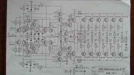
Here is the schematic with measured potentials. Still only one channel built, sorry.
Attachments
Assembled second channel - the same voltage drop on 15V zeners. Perhaps when I had 15V on those zeners the pots were set to 100Ohm - without load.
The only conclusion can be that some of my new to92 transistors are faulty or it's correct behavior for zeners with such a load. However, they are 5W types Onsemis 1N5352BRLG
The only conclusion can be that some of my new to92 transistors are faulty or it's correct behavior for zeners with such a load. However, they are 5W types Onsemis 1N5352BRLG
Yes, reworked from Alex MM design.
Dedegogo, could you please give your thoughts on second ch. results? Schematic is through 3 posts earlier.
I think that you have more than 10mA or 20v across the 2k2. So what is causing the huge current draw?
Dedegogo, could you please give your thoughts on second ch. results? Schematic is through 3 posts earlier.
Last edited:
- Status
- This old topic is closed. If you want to reopen this topic, contact a moderator using the "Report Post" button.
- Home
- Amplifiers
- Solid State
- CFP Amplifier - Help Please!