Yes, sure.
I would rate main 4700uF power rail caps at 50v and specify max rails at +/-45v.
2200uF caps at VAS are also 50v rating
2200uF caps at input are 16v rating
10uF caps are MLCC 50v 5mm pitch radial leads
100nF caps are MKT 100v 5mm pitch radial leads
10pF cap is C0G/NP0 or silver mica 2.5mm leads
1uF cap is MKT 63v 5mm pitch radial leads
10uF input cap can be electrolytic but preferably film with 250v rating, 30mm pitch radial leads. Provide option for 5mm pitch electrolytic if someone wants to keep it simple
1n4148 and 12v Zener are usual 1w 1a axial leads
Electrical terminals are 0.250in wide FASTON style PCB spade solder tabs with 5mm pitch and 1.8mm dia holes.
Trimpots are blue Bourns style multi turn with brass screw and 3 legs in straight row.
All resistors are 0.25w metal film 1% unless otherwise specified.
R12, R13 are 2w 5%
R14, R16 are 1w 5%
R2? R3, R6, R7, R17, and R19 are 0.5w 1%
Schematic was simulation condition and although it's possible to run amp at 53v, I was thinking reducing rails allows smaller less expensive 50v caps to be used. Although if you want a 150w amp - leave it at 53v and specify 63v caps on 4700uF and 2200uF VAS caps and 24v on 2200uF input caps. The amp will indeed run at 53v as I have demonstrated it before. Some of the MLCC caps then need to be increased to 63v rating.
The board will be the same for either voltage so doesn't matter unless you will be specifying voltages for caps on silkscreen.
The board will be the same for either voltage so doesn't matter unless you will be specifying voltages for caps on silkscreen.
Last edited:
Original idea of my first "Very Smooth Sounding Amplifier" is based on a vintage japanese schematic as well. Published in 1999 (H&T Magazin) built in 2000. Still working fine. XRK is right, gaborbela was the first who discussed this topology here in detail. Lazy Cat's schematic has some additional refinement: LatFET output, higher feedback, precision shunt regulator for rock steady VAS current, low noise JFET CCS, better lag compensation and many other things what makes him design unique. XRK walking on same avenue as shaan does: Keeping this circuit as simple as possible.
Thanks for the info guys, it clears so much.
")
Even first letters of the name "Very Smooth Sounding Amplifier" matches my "Very Simple Symmetrical Amplifier", how cool that can be. Obviously there really are limited number of odds to set simple amplifier topology, so eventually people came to the same conclusions/solutions playing around.
VSSA and all similar topologies are based on singleton ie. single transistor amplifying stage going symmetrical, from there on things are trivial.
VSSA specialty is using laterals, logical choice since no extra thermal compensation needed for the outputs to be in stable operating conditions. Also very easy to drive concept of laterals is perfect match to VSSA topology. All in all resulted in a very popular VSSA amplifier topology spreaded all around the world, seen even today here in this thread.
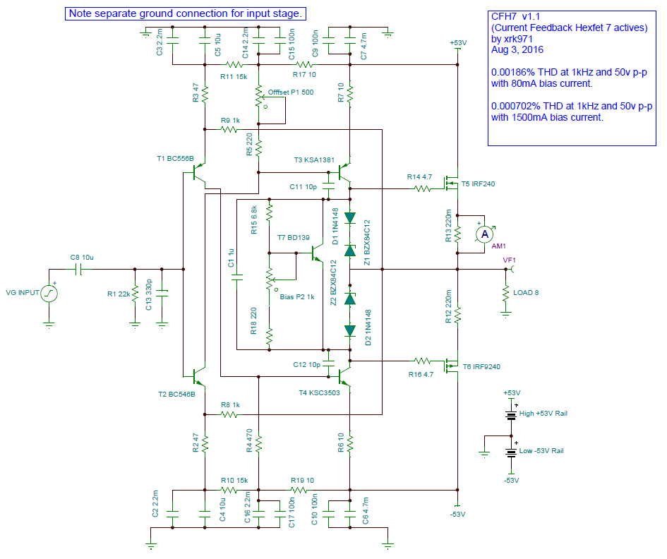
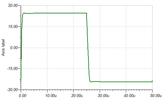
Final v1.1 (I think) schematic. I added some more power rail caps to put a CRC between the main MOSFET output caps and the VAS rail caps. Added trim pot to xero out DC offset. Distortion is still really good (looks like if you run in class A with 1.5a bias, distortion is really low). Square waves resemble what I presented before so I won't show again. This amp is good out to almost 1Mhz.
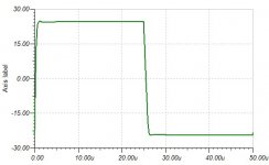
Add 470nF in parallel with 8R load and look 20kHz square waves.
Oh well, where to start... TIP 142-147 continue blowing well before reaching the + - 35VDC rail target, THD 1 watt 20Khz a mediocre 0.08%, FFT at 1W 20Khz shows a spray of harmonics, the odd ones clearly dominant throughout...
http://www.diyaudio.com/forums/solid-state/276360-darlington-vssa.html
Your s instead, shows excellent result from the start on.
I design amplifier like this, too (VSSA with BJT output). Very high slew rate, tested by my friend a year ago. I did not hear he complaint about blow up transistors or the quality of my design.
But, I did not remember exactly which design. Because, I have so many simulation of this kind amplifier
I design amplifier like this, too (VSSA with BJT output). Very high slew rate, tested by my friend a year ago. I did not hear he complaint about blow up transistors or the quality of my design.
But, I did not remember exactly which design. Because, I have so many simulation of this kind amplifier
So the high slew rate observed in sim is not imagined. Good to hear that and encouraging for us to proceed down path of PCB layout and manufacturing.
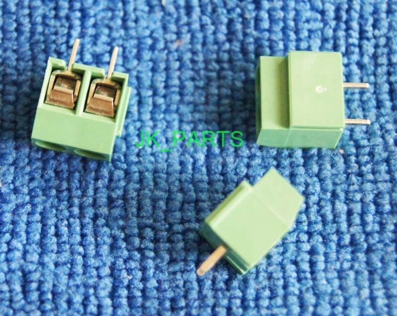
@Idefix: if you like SMT for NP0/C0G 10pF bypass caps I am good with it too. I agree they are superior for getting close to the pins. I do have some very small radial lead C0G ceramic caps though on hand. Whatever you like is good as you are the layout artist - can be your discretion. I do have one request though and that's my preference for two position 5mm screw terminal block (1.5mm holes) for audio input. I don't like 0.10in pitch header pins.
@Apex Audio: I will run sim and see how it looks with a capacitive load. Perhaps a 1uH coil and 10R Thiele network on output may be in order to ensure stability?
NP0 C0G SMT question
Typically we get only low voltage ( 50 or 63 V) SMT caps in the local retail market.
If we want something slightly higher , say for use in +/- 60 V rails circuit where the voltage across the cap can exceed 60 V,
would it be safe to use two in series. They will not share the voltage equally due to parameter variation but I suppose the variation would still be on the safe side ?
Take a look at TME.eu you will find smd 1206 form over 50V. In 100V rating they have 10pf/47pf/100pf/220pf/330pf...
Marc
I do have one request though and that's my preference for two position 5mm screw terminal block (1.5mm holes) for audio input.
Have you an exemple or a link?
Marc
the C||R test is to see overshoot, if any, on fast transients. That gives a clue on stability and margins................@Apex Audio: I will run sim and see how it looks with a capacitive load. Perhaps a 1uH coil and 10R Thiele network on output may be in order to ensure stability?
Do not isolate this from the amplifier.
The R||L between the amp out and the enclosure speaker terminal is to isolate cable capacitance and severe reactance speakers from creating excessive phase loading of the amplifier. This is quite different.
I am surprised that no amp output Zobel is being specified.
Add 470nF in parallel with 8R load and look 20kHz square waves.
Apexaudio:
Thanks for pointing out potential capacitive loads for an amp to deal with.
Here is the 20kHz square wave with a 470nF load in parallel to 8R resistive load - not pretty with all that ringing:

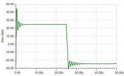
So I went in and added a snubber and a Thiele network which cleans it up nicely, but the slew rate suffered a bit. For lower distortion speaker sound with typical capacitive (reactive loads), giving up some slew for less ringing is probably a good tradeoff. Here is 20kHz square wave with 470nF and 8R load but with 4.7R+100nF snubber and 2uH+0.47R Thiele in place:
New schematic with above mods, the THD with a 470nF and 8R load with new circuit is now 0.00503%, still a decent figure I think:
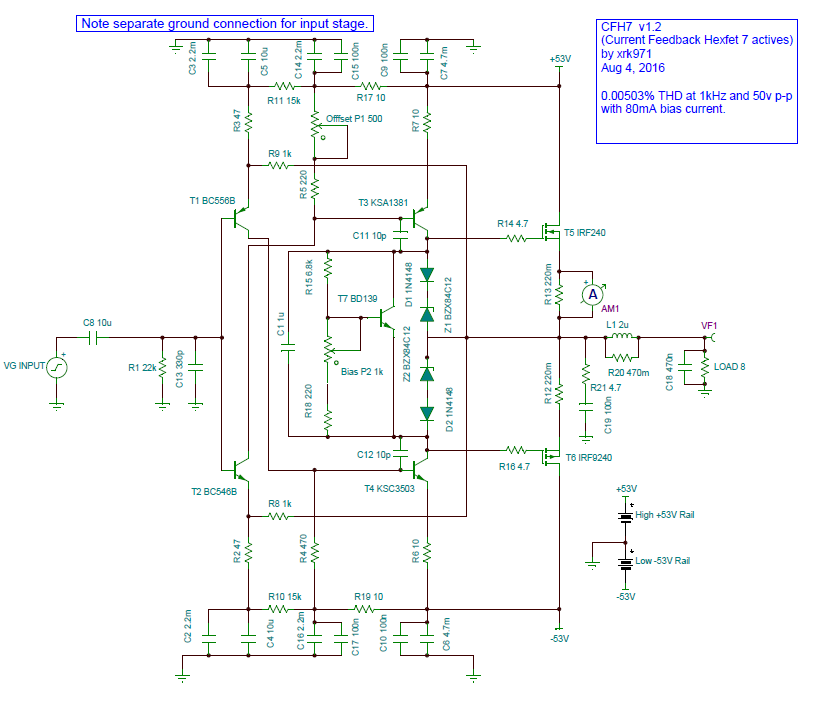
4 more parts to the output. I was surprised that a 0.47R in parallel with the 2uH gave the best result (this was tweaked for optimal square wave rise and minimum ring and overshoot). Usual values are circa 10R and 1.2uH.
But, if you plan to use this as an amp to direct drive an active speaker driver with no capacitive load cross-over, use the V1.1 circuit (bypass the snubber and Thiele network) for the highest slew rate with lowest distortion. But if using conventional passive speakers with capacitive elements in crossover, better to use v1.2.
Edit: @AndrewT, is the Zobel the same as my RC snubber?
Attachments

Last edited:
Have you an exemple or a link?
Marc
Like this:
20pcs 5mm Pitch 2 Pin 2 Way Straight Pin PCB Screw Terminal Blocks Connector | eBay
last first.Apexaudio:
Thanks for pointing out potential capacitive loads for an amp to deal with.
Here is the 20kHz square wave with a 470nF load in parallel to 8R resistive load - not pretty with all that ringing:
So I went in and added a snubber and a Thiele network which cleans it up nicely, but the slew rate suffered a bit. For lower distortion speaker sound with typical capacitive (reactive loads), giving up some slew for less ringing is probably a good tradeoff. Here is 20kHz square wave with 470nF and 8R load but with 4.7R+100nF snubber and 2uH+0.47R Thiele in place:
New schematic with above mods, the THD with a 470nF and 8R load with new circuit is now 0.00503%, still a decent figure I think:
4 more parts to the output. I was surprised that a 0.47R in parallel with the 2uH gave the best result (this was tweaked for optimal square wave rise and minimum ring and overshoot). Usual values are circa 10R and 1.2uH.
But, if you plan to use this as an amp to direct drive an active speaker driver with no capacitive load cross-over, use the V1.1 circuit (bypass the snubber and Thiele network) for the highest slew rate with lowest distortion. But if using conventional passive speakers with capacitive elements in crossover, better to use v1.2.
Edit: @AndrewT, is the Zobel the same as my RC snubber?
Yes the "snubber" is the same as the amplifier output Zobel.
It is extremely unusual to see any power amplifiers without a Zobel to load the amplifier at high frequency. Some Pass designs and one commercial design (name escapes me).
But you are doing the test incorrectly.
The capacitor is being tested to reveal clues about stability margins.
Do not isolate it from the amp output stage by fitting it after the isolating network of the R||L
At high frequencies the sim is modelling the L as near open circuit and what the sim then models is an R + testC, i.e. a duplication of your snubber. No wonder the overshoot disappears.
Attach the test probe to the amp out, not across the 8r0 dummy load.
Last edited:
The capacitor is being tested to reveal clues about stability margins.
Do not isolate it from the amp output stage by fitting it after the isolating network of the R||L
At high frequencies the sim is modelling the L as near open circuit and what the sim then models is an R + testC, i.e. a duplication of your snubber. No wonder the overshoot disappears.
So rerun the sim with the 470nF at same location as Zobel snubber?
Attach the test probe to the amp out, not across the 8r0 dummy load.
So where is test probe voltage with reference to if not ground and dummy load? I am confused - maybe a sketch would help. But I honestly thought Apex's point was to show that a bare bones output to a purely resistive load won't look so pretty if the load is a tiny bit capacitive in nature. If it were, and I think passive XO loads are, the R//L will help immensely.
Last edited:
Yes, the C & the snubber and the measurment probe all go the amp out.
You then get to see what the amp tries to do when presented with a fast transient.
But not too fast. Where is your RF attenuation set for frequency? 500kHz, or 1MHz, or 1000MHz?
At the moment that 330pF see no preceding impedance so it cannot operate as an RF filter. The amp sees an ultra fast step response set by your step rise/fall time.
Don't be unrealistic. Set it to somewhere around 10x to 100x the maximum audio frequency of 20kHz i.e. somewhere between 200kHz and 2MHz. See what the amp does with those two filter values after the source step function.
Last edited:
- Home
- Amplifiers
- Solid State
- CFH7 Amp