Well I did the calculations assuming Vbe of 0.56v and using two red LEDs for a voltage drop of 3.5v (as measured for the types that I have). I arrived at 6.8k on top, same 1k pot and 680R bottom resistor (vs old 220R). However when I put this in the sim it doesn't work. In any event - I have been happy with using a BD139 and these resistor values for controlling bias on other IRFP240 based amps and it had worked fine. So I don't think I am going to change it. Why fix it if it's not broke? Successfully used on FH9, FH9HV, FH11/12. No need to change it as I think the serendipitous combo of heat sink time constant and higher correction gain all work out well.
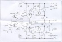
So final schematic is like in post 1 with addition of wire between middle of Zener string to the output node. That's it.
@Idefixes: if you could be so kind as to work up a PCB layout that would be most appreciated. Please keep compact under 100mm x 100mm and underhung FETs or standing up 90 deg FETs on one edge. Thank you.
Last edited:
Just to inform all of you, VSSA (Very Simple Symmetrical Amplifier) is my amp and it was sold in hundreds few years ago. Its successor is First One S which will be released this year. More in below VSSA link.
BTW Gaborbela is not electronic guy, he took sch from god knows where, so to be correct the original author of this topology is unknown.
I came to VSSA sch from my SSA and TSSA schematics from naturally developing the concept and did not know anything about the guy and his drawings. Just to be clear.
Hi Lazy Cat,
Lot of similar designs are available in Japanese DIY sites.20-35 years old.

Hi Lazy Cat,
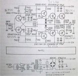
Lot of similar designs are available in Japanese DIY sites.20-35 years old. View attachment 562956
Original idea of my first "Very Smooth Sounding Amplifier" is based on a vintage japanese schematic as well. Published in 1999 (H&T Magazin) built in 2000. Still working fine. XRK is right, gaborbela was the first who discussed this topology here in detail. Lazy Cat's schematic has some additional refinement: LatFET output, higher feedback, precision shunt regulator for rock steady VAS current, low noise JFET CCS, better lag compensation and many other things what makes him design unique. XRK walking on same avenue as shaan does: Keeping this circuit as simple as possible.
Attachments
Last edited:
Just to inform all of you, VSSA (Very Simple Symmetrical Amplifier) is my amp ......
BTW Gaborbela is not electronic guy, he took sch from god knows where, so to be correct the original author of this topology is unknown.
I came to VSSA sch from my SSA and TSSA schematics from naturally developing the concept and did not know anything about the guy and his drawings. Just to be clear.
If you came to a similar or same 'old' circuit on your own, it's perfectly fine.
However don't cut other people down by making such negative statements about Gaborbela. He never claimed it was his circuit either . Incidentally a LOT of members here are NOT 'electronics guys'. It also looks as if the original came from Japan ! It really doesn't matter who exactly it is. It's an interesting circuit that works well. Many people have refined it in some way or other.
He brought it back to our notice and many people had a great time experimenting with it. Thanks should be due to him for that. Thanks to all the forum members who bring to our attention circuits that actually are worth checking out , no matter how new or old they are. That's what's great about this forum !
so to be correct the original author of this topology is unknown.
First DIY known publication was surely on japanese mag MJ in the 70s..
Attachments
That's over 40 years ago ! That's a long time. Wonder if there were any commercial amps built with similar topology. Must have been I guess. I have a book of Jap amp circuits printed in 1980. A few hundred pages with circuits on either side of a page. I'll scan it all one of these days and see if it's legal to post it on some site, maybe Pete Millet's site ?
About 216 pages...about 432 sides of diagrams. Plus more pages in front ( about a 100 sides!) with several diagrams again and some theory....all in Japanese of course ! It was almost lost and I found it but time has taken it's toll and its better to scan it all before it 'dies' !
About 216 pages...about 432 sides of diagrams. Plus more pages in front ( about a 100 sides!) with several diagrams again and some theory....all in Japanese of course ! It was almost lost and I found it but time has taken it's toll and its better to scan it all before it 'dies' !
Last edited:
")
Wonder if there were any commercial amps built with similar topology. Must have been I guess.
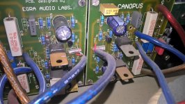
There s the Nakamichi E210, albeit with a more sophisticated circuitry that is somewhat beyond usual DIY capabilities and fun...
Attachments
I see that I should probably add a trim pot on one leg of the supply feeding the inputs to allow for DC offset adjustment.
I measured the DC offsets: 1mV and 3mV after 16yrs. Input BC's were only matched.
Proposal for PCB design: use separated ground header for input section. Thimios pointed that the split ground pays well (PeeCeeBee v2)
Egra, you mean like add a 10R ground lift resistor to signal input ground?
No. Using a separate ground wire from power supply to input stage. This results cleaner signal ground than using 10R to dirty ground. Check this layout:
http://www.diyaudio.com/forums/solid-state/231662-peeceebee-195.html#post4627806
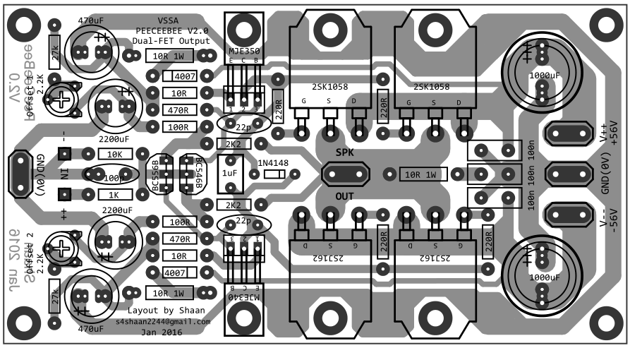
Ok, I see a separate ground pin and circuit on the left side for the input stage. This will make the PSU the star ground hub then?
...
It makes the circuit a little more complicated to layout.
Since the overall circuit is pretty simple, the added tracks will not really make complicate the layout. If I remember correctly shaan has measured the difference between two grounding techniques so feel free to ask him.
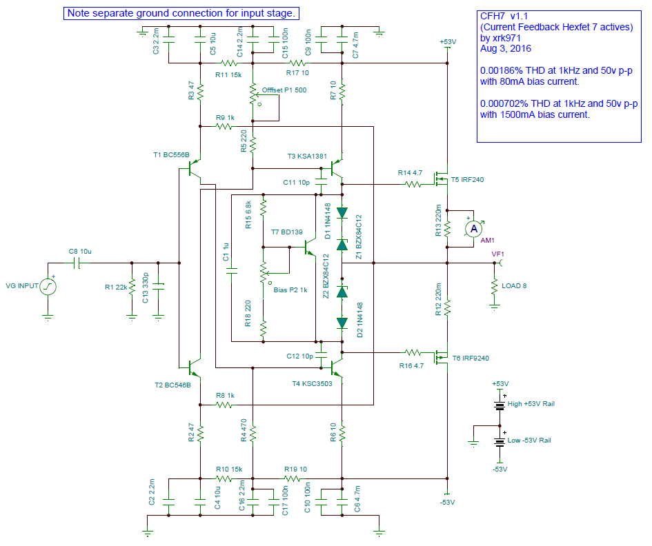
Final v1.1 (I think) schematic. I added some more power rail caps to put a CRC between the main MOSFET output caps and the VAS rail caps. Added trim pot to xero out DC offset. Distortion is still really good (looks like if you run in class A with 1.5a bias, distortion is really low). Square waves resemble what I presented before so I won't show again. This amp is good out to almost 1Mhz.
Attachments
- Home
- Amplifiers
- Solid State
- CFH7 Amp