If I understand it is about the application of a negative output resistance by known methods in the subwoofer, for example:
Variable Amplifier Impedance
Effects Of Source Impedance on Loudspeakers
These methods are applicable only in a frequency range not higher than 300 Hz, and have serious drawbacks.
Furthermore the author Effects Of Source Impedance on Loudspeakers
conducted research at output impedance minus 3 ohms!
Getting a negative impedance with a positive operating current output shifted relative to the input voltage is not the best way.
According to my information to make the output impedance more negative than minus 0.3 Ohm undesirable, there are problems at frequencies of 100 ... 200 Hz - to "depression" impedance of the subwoofer.
Therefore, I think that put the stamp on the negative output impedance of the amplifier only on the basis of failed experiments is extremely cautiously, especially because the subwoofer is not responsible for the reproduction of mid-range, where the largest concentration range signals.
Originally Posted by ontoaba
I am asking the schematic available to built or amp available to buy, of your friend's amp, so I could compare with my natural amp. I like good sounded amps, thats all. Please any link?
The problem of negative output impedance is the resonance of the voice coil inductance, Le, with the capacitive value, Ces, of the motional impedance.
As Le has a variable value with both frequency and voice coil position in the gap, negative impedance, if a high absolute value is desired (always less than Re !) , needs to seriously study the circuit and the driver to set the necessary compensations.
An attenuator of 1 kOhm /1 kOhm at the input of a non-inverting amp can provide a negative impedance output. The second 1 kOhm is connected to a 0.33 or 0.47 Ohm power resistor inserted between the loudspeaker and ground. This scheme is a positive feedback.
The amp can be of non-GNFB kind.
Sorry, but D.S has a limited and a little too definitive view of this question, on my opinion. Just think about thermal effects in transistors, charges in capacitances etc. very different between a *constant energy* combination of sinus waves, and a musical signal, where the ratio peak/average is important and constantly variable. As well the frequency repartition between an instrument and an other.About sinewaves claimed inaccurate for test-signals :
I don't understand the interest of quoting vulgarization articles, it don't prove anything.
D.S has his own point of view. You seems to agree with him on this point ? I don't.
By the way, i build CFAs amp, he don't.
Last edited:
Sorry, but D.S has a limited and a little too definitive view of this question, on my opinion. Just think about thermal effects in transistors, charges in capacitances etc. very different between a *constant energy* combination of sinus waves, and a musical signal, where the ratio peak/average is important and constantly variable. As well the frequency repartition between an instrument and an other.
I don't understand the interest of quoting vulgarization articles, it don't prove anything.
D.S has his own point of view. You seems to agree with him on this point ? I don't.
This being said, if you are denying a century of development in signal processing(from Fourier transform to feedback theory), and call DS's explanations "vulgarization", then there's indeed nothing left to debate. There are obviously no arguments that you will ever accept.
Deep space communications, CT scanners, the Higgs boson discovery, all these, and many other, rely on these fundamental principles. And though, somehow, when it comes to audio, they can be denied and tossed in the mud.
Amusing.This being said, if you are denying a century of development in signal processing(from Fourier transform to feedback theory), and call DS's explanations "vulgarization", then there's indeed nothing left to debate.
Joseph fourrier is dead around 1830 and was a mathematician. Feedback theories were developed long before i was born, and, i'm sorry, but:
"I think this view must be the result of anthropomorphic thinking about
amplifiers; twenty sinewaves of different frequencies may be conceptually more
complex to us, but to an amplifier it resolves to a single instantaneous voltage
that must be increased in amplitude. An amplitude. An amplifier has no
perspective on the signal arriving at its input, but must take it as it comes;"
is a personal opinion, non a scientific demonstration. The signal itself modify the amplifier behavior and the amp is not the same before and after.
Welcome back in my ignore list to assign me words that I did not say, and do personal attack, as usual.
Last edited:
Motional Feeedback results 1985
Here is how it was done - (c) Marsh 1985
Part of a "Low-Feedback Amp Design" [VFA") ]:
]:
It works better with high gnfb amps, I suspect. It does reduce the amount of nfb at the resonance freq. Less neg fb could be considered positive fb but it is just less negative feedback. I never tried other values nor other amps... just a test of concept. This amount of acoustic reduction in distortion is very audible at these THD reduction levels.... and well worth doing in any system.
I always try to throw in something extra in my articles - this was about the amp circuit but threw in the motional feedback at the end. Like spices. This was shown else-where in DYIAudio months ago.
I just lifted the gain resistor to ground of this amp and in serted the sampling resistor... l then rerouted the -(neg) speaker wire over to this sampling resistor and connected another large gauge wire from the pcb (-) wire point back to the ground at the power supply.
View attachment MFB ckt_1.pdf
View attachment MFB_2.pdf
How well would this work with a CFA? Or for just a sub amp with high gnfb?
[BTW... the simple VFA circuit, low feedback, measured .008% THD+N at 20KHz, 1dB below clipping. 28 yrs ago]
Thx-RNMarsh
An attenuator of 1 kOhm /1 kOhm at the input of a non-inverting amp can provide a negative impedance output. The second 1 kOhm is connected to a 0.33 or 0.47 Ohm power resistor inserted between the loudspeaker and ground. This scheme is a positive feedback.
The amp can be of non-GNFB kind.
Here is how it was done - (c) Marsh 1985
Part of a "Low-Feedback Amp Design" [VFA
]: It works better with high gnfb amps, I suspect. It does reduce the amount of nfb at the resonance freq. Less neg fb could be considered positive fb but it is just less negative feedback. I never tried other values nor other amps... just a test of concept. This amount of acoustic reduction in distortion is very audible at these THD reduction levels.... and well worth doing in any system.
I always try to throw in something extra in my articles - this was about the amp circuit but threw in the motional feedback at the end. Like spices. This was shown else-where in DYIAudio months ago.
I just lifted the gain resistor to ground of this amp and in serted the sampling resistor... l then rerouted the -(neg) speaker wire over to this sampling resistor and connected another large gauge wire from the pcb (-) wire point back to the ground at the power supply.
View attachment MFB ckt_1.pdf
View attachment MFB_2.pdf
How well would this work with a CFA? Or for just a sub amp with high gnfb?
[BTW... the simple VFA circuit, low feedback, measured .008% THD+N at 20KHz, 1dB below clipping. 28 yrs ago]
Thx-RNMarsh
Last edited:
a personal opinion, non a scientific demonstration. The signal itself modify the amplifier behavior and the amp is not the same before and after.
The quiescent current of the output stage is somewhat dependant of the power dissipated and found to be in tiny relation with the signal.
Some auto-bias circuits as proposed by Marcel van de Vegel or Edmond Stuart may solve this problem.
Output stage apart, saying that the signal modifies the amplifier behavior is not a scientific demonstration, it has to be proven.
Well known french Hephaïstos designed clever circuits not suffering from what was called input thermal distortion and later became known as memory distortion.
But there are major problems : Hephaïstos him-self failed to demonstrate the existence of this memory distortion on standard amp configurations with differential inputs. Nobody did better.
I have done my own little researchs on memory distortion submitting an input differential stage to a 4 Vrms signal and concluded that all the Hephaïstos stuff , albeit fascinating me, was based on non-significant effects with a voltage four times the usual value for an amp input.
This quote taken from Douglas Self's book is 100% correct. Thanks for posting it.
I did the quote :
http://www.diyaudio.com/forums/solid-state/240712-cfa-topology-audio-amplifiers-102.html#post3703292
Esperado is not Self freak...

Perhaps you're confusing 'reactive' with 'non-linear' - I wasn't referring to reactive loads. A speaker is non-ohmic in the sense that when driven with a zero-distortion sine, it draws a non-zero distortion current. Imposed across any impedance in the output circuit this distorted current gives rise to voltage distortion. Those aiming for multiple zeros after the point in THD will do well to bear this in mind.
Perhaps the paper you're referring to is this one? Loudspeakers: Effects of amplifiers and cables - Part 1 | EE Times
(I have Newell and Holland's book).
The aim of negative feedback in voltage amps aim is to instantaneously and precisely control the voltage output.
Any undesired voltage at the output, whatever its origin, is reduced by negative feedback in a manner detailed in many books.
The undesired voltage due to your non-zero distortion currents is not treated differently.
If it is otherwise, you have to prove it.
I am curious of examples of the amount of distortion of these currents and how they change the output a good amp having low distortion with no load.
A good experience would to short the amp input and inject any kind of current at its output and observe the output voltage and its distortion.
Amps having THD with multi-zeros after the point generally costs less than others... The CFAs costs have not been adressed.
almost everything about an amplifier's output at audio frequencies into complex speaker loads can be seen with a "tug-of-war" test - a (bigger) amp on the other end of a power R load - driven with phase shifted test signal
you can also drive the other end of the power R with different frequencies, multi-tones, emulate nonlinear loads
Exactly!
Cheers,
Bob
Yes. Perfectly right.almost everything about an amplifier's output at audio frequencies into complex speaker loads can be seen with a "tug-of-war" test - a (bigger) amp on the other end of a power R load - driven with phase shifted test signal
you can also drive the other end of the power R with different frequencies, multi-tones, emulate nonlinear loads
We felt more simple to use real speakers in the basement (to not be bored by the noise). Boomers in a vented box, +horn drivers powerful enough to afford high power sinusoidal or square frequencies for such measurements.
Hard to be closer to real life
About creating complex signals with sinus combinations, it makes-me remember the early beginning of rhythm boxes. Hours to program in studio what a drummer can do hundred time better on the fly ;-)
Just a little story to feed the thoughts: The first time i tried a prototype of my protection circuit on my amp, (It compare output and input signals) it was carefully set to be stable with sinus waves between 10 and 20 000Hz at full power. The first kick drum at much lower level fired the protection.
Last edited:
Force it to be sounded like the real one, not forcing it with voltages that makes it sounded like any annoying sound.Did-we want to listen to the 'natural' sound of loudspeakers, or force them to reproduce closer the music ?
Thanks, the sch, in page 57, sch is using negative feedbak locally for error correction. Looks like the sound is good coming from another also.Description amplifier with negative impedance and without general NFB at the end of the magazine log at: [/COLOR]
Ðàäèîõîááè ¹4 (àâãóñò 2013)
best regards
Petr
I would be interested in reading the whole article. Where was it published and is it still available ?
3/1985 The Audio Amateur.
-RNM
Here is how it was done - (c) Marsh 1985
Part of a "Low-Feedback Amp Design" [VFA
It works better with high gnfb amps, I suspect. It does reduce the amount of nfb at the resonance freq. Less neg fb could be considered positive fb but it is just less negative feedback. I never tried other values nor other amps... just a test of concept. This amount of acoustic reduction in distortion is very audible at these THD reduction levels.... and well worth doing in any system.
I always try to throw in something extra in my articles - this was about the amp circuit but threw in the motional feedback at the end. Like spices. This was shown else-where in DYIAudio months ago.
I just lifted the gain resistor to ground of this amp and in serted the sampling resistor... l then rerouted the -(neg) speaker wire over to this sampling resistor and connected another large gauge wire from the pcb (-) wire point back to the ground at the power supply.
View attachment 382377
View attachment 382379
How well would this work with a CFA? Or for just a sub amp with high gnfb?
[BTW... the simple VFA circuit, low feedback, measured .008% THD+N at 20KHz, 1dB below clipping. 28 yrs ago]
Thx-RNMarsh
View attachment 382377 is different from the scheme what I refered.
In View attachment 382377 , with a constant signal, for low impedance of the load, voltage across the 0.15 Ohm shunt resistor increases and there is more fedback voltage. The whole voltage gain decreases. The amp output impedance increases : more current in the load, less output voltage.
In the scheme I refered, with an attenuator at the input and its "foot" resistor connected to the shunt resistor in the load path, the input voltage, which is less submitted to division due to the bootstrap effect, increases for low impedance of the load, and the amp output decreases and becomes negative : more current in the load, more output voltage.
Another negative resistance scheme, conceptually very smart, consists of an inverting power amp. The non-inverting input, instead of being connected to ground, is connected to the shunt resistor, possibly via a pot to set the amount of positive feedback.
Calculations are easy, but tests need precautions against excessive currents and unexpected behavior on reactive loads.
Regards.
I don't understand. If the whole whole voltage gain decreases, it means there is more NEGATIVE feedback, so, the output impedance will *decrease* ?The whole voltage gain decreases. The amp output impedance increases : more current in the load, less output voltage.
Anyway, as much speakers manufacturers try their best to sell flatest possible response curves in correlation with *voltages*, and most of the time don't care about impedance curves, i don't see any interest in making the system less flat, and less damped.
As kgrlee pointed earlier, speakers (any exception ?) are NOT designed to be current driven.
The ideal output impedance of an amp is 0. having a little negative can compensate resistances in cables. Going further, we enter in the "servo controled" speakers world, where speakers and amp have to be designed one for the other, IE self powered enclosures.
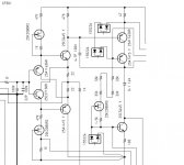
As some object to the use of symmetrical CFA I ll post an example of a commercial unsymmetrical CFA using diamond buffer. Unsymmetrical CFA does not neccessarily mean it has to use a single input transistor topology with emitter feedback. This is the inputstage of a 400w amp by well known and respected japanese manufacturer.
Attachments
Last edited:
As some object to the use of symmetrical CFA I ll post an example of a commercial unsymmetrical CFA using diamond buffer. Unsymmetrical CFA does not neccessarily mean it has to use a single input transistor topology with emitter feedback. This is the inputstage of a 400w amp by well known and respected japanese manufacturer.
Manso, I have sent you email twice but no answer.
BR Damir
As some object to the use of symmetrical CFA I ll post an example of a commercial unsymmetrical CFA using diamond buffer. Unsymmetrical CFA does not neccessarily mean it has to use a single input transistor topology with emitter feedback. This is the inputstage of a 400w amp by well known and respected japanese manufacturer.
Is this a bridge amp? If so, the whole circuit may be symmetrical. Why did you cut off the interesting parts??
Jan
yes, it read as different..... my way is simple and any DIY'er can try it on their own existing amp. And, I showed the practical end result. Cant get any simpler than one resistor.
[Something about simplicity that I like. ]
Anyway, you might try your idea on your amp and see how it makes your speaker perform and if you hear an improvement. Should not take you long to implement and give us the feedback ( )
-RNM
[Something about simplicity that I like.
]Anyway, you might try your idea on your amp and see how it makes your speaker perform and if you hear an improvement. Should not take you long to implement and give us the feedback (
)-RNM
View attachment 382377 is different from the scheme what I refered.
In View attachment 382377 , with a constant signal, for low impedance of the load, voltage across the 0.15 Ohm shunt resistor increases and there is more fedback voltage. The whole voltage gain decreases. The amp output impedance increases : more current in the load, less output voltage.
In the scheme I refered, with an attenuator at the input and its "foot" resistor connected to the shunt resistor in the load path, the input voltage, which is less submitted to division due to the bootstrap effect, increases for low impedance of the load, and the amp output decreases and becomes negative : more current in the load, more output voltage.
Another negative resistance scheme, conceptually very smart, consists of an inverting power amp. The non-inverting input, instead of being connected to ground, is connected to the shunt resistor, possibly via a pot to set the amount of positive feedback.
Calculations are easy, but tests need precautions against excessive currents and unexpected behavior on reactive loads.
Regards.
Is this a bridge amp? If so, the whole circuit may be symmetrical. Why did you cut off the interesting parts??
Jan
No, the symmetrical parts some seem to be against is the vas for whatever reason. Current mirrors can be used to obtain better symmetry in the diamond as its only loaded on one side. It has fet drivers driving 5 pairs of vertical fets per channel and wheighs in at 70kg.
I posted it because of a discussion I had with bigun who I think didnt quite understand the concept I was explaining to him.
I didnt post the whole circuit as I dont fancy having my nether parts kicked by the manufacturer in case he prohibited it.
- Home
- Amplifiers
- Solid State
- CFA Topology Audio Amplifiers