I had a look at noise performance, Substituting the OPA627's in the simulation with ideal noiseless opamps made very little improvement (a couple of microvolts only). That suggests that the dominant noise source is the resistors in the filters. So I'm not too surprised that swapping opamps made not much difference. I think that FET input opamps will have the noise edge as compared with bipolar. Bipolar current noise is orders of magnitude higher than JFET, and since the resistors are rather high value current noise can easily dominate..
I was thinking about DC offsets in the Palette Preamp. First, looking at Burwen's original IC-based design for the Audio Palette, he used 6 DC servos per channel to remove offsets around switches to make their action click-free.
Also Curl made use of servos in both the Vendetta phono stage and in the famed and infamous Blowtorch.
And Bob Cordell used them in his VinylTrak phono stage (a mix of discrete and IC stages)
The benefit is that it keeps DC blocking capacitors, often electrolytic, out of the audio chain
Now these have to be designed with care to be (a) stable (ie don't oscillate) and (b) acoustically transparent (free of phase shift and peaking) and (c) have the right capture range (IOW don't hit the rails before they have nulled the offset. But there are plenty of road tested designs out there.
Time to do a bit of simulation...
Craig
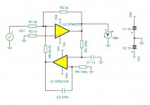
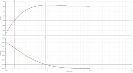
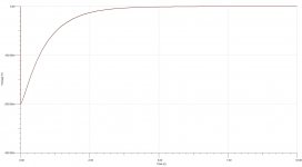
Simulation result for one of the Burwen servos.
The -3dB point is 0.18Hz, and 10 degrees phase shift is at 0.9Hz. Both safely outside the audible range. The servo amp has to be low distortion, because it is still partially in circuit well into the audio band. The transient response is good with no overshoot or ringing. It is configured around a -1 gain amp.
The servo IC output voltage is 20x the DC input voltage offset. So it can cope with ~0.75V of offset before the servo amp hits the rails. For more modest offsets of a few tens of mV, the output is within a few microvolts (<<10uV) of zero,
The main op-amp in the simulation is an OPA827. The original Palette Preamp ICs were OPA627 (which are still available). But the design was upgraded to the OPA827, and a recently introduced OPA828. That is a superb FET input device, with 150V/us slew rate, and better noise and offset performance than the OPA627. Although these are out of stock until April next year I have 5 samples on their way from TI. 8-pin SOIC. The added benefit is that the OPA828, when it becomes available again, is much cheaper than the OPA627.
Attachments
It is fun to build stuff, but if you should want to buy, this looks good. No op-amps, and LC's.
https://www.schiit.com/products/loki-mini-3
https://www.schiit.com/products/loki-mini-3

Wonder why they say this when it looks like there are op-amps in the picture? Maybe the Mini+ is the one without op-amps.
"Loki Mini+ uses a single, discrete, current-feedback gain stage, coupled to passive LC filters for 3 bands, plus a gyrator for the bass."
Those inductors look like they use ferrite, which I don't like the sound of.
"Loki Mini+ uses a single, discrete, current-feedback gain stage, coupled to passive LC filters for 3 bands, plus a gyrator for the bass."
Those inductors look like they use ferrite, which I don't like the sound of.
I'd say they were definitely op amps. Surface mount transistors look entirely different - either three pad for single transistors, or for duals five (for eg commoned emitters) or six for two independent transistors. Peering at the picture there are in fact four six-pad dual and a number of single transistors, and a bunch of opamps.
But although inductors have been used in a number of designs (see much earlier in this thread) they are the most imperfect of electronic components. If nothing else they suffer from proximity effect (which compromises HF Q) and self resonance as a result of winding capacitance. Not counting magnetic non-linearity of the core.
High quality capacitors and metal film resistors are many orders of magnitude more predictable than inductors.
https://www.rfcafe.com/references/e...s-control-electronics-world-december-1963.htm
Just a simple passive loudness control can really help poor recordings and listening at low volume. I have built this circuit with the addition of a small cap (500-1000pf) across the top half of the pot, similar to the circuit shown in figure 2.14.11 in the National Semiconductor Audio/Radio Handbook 1980. This is similar to the “BBC dip” effect. The benefit of this is that it is all passive, no op-amps, ferrite inductors. Could a all passive RC multi-band cut only EQ be built with this type of circuit? I realize that RC is 6db/Oct and LC is 12db/Oct. But maybe 6db would sound good in for some applications.
Just a simple passive loudness control can really help poor recordings and listening at low volume. I have built this circuit with the addition of a small cap (500-1000pf) across the top half of the pot, similar to the circuit shown in figure 2.14.11 in the National Semiconductor Audio/Radio Handbook 1980. This is similar to the “BBC dip” effect. The benefit of this is that it is all passive, no op-amps, ferrite inductors. Could a all passive RC multi-band cut only EQ be built with this type of circuit? I realize that RC is 6db/Oct and LC is 12db/Oct. But maybe 6db would sound good in for some applications.
I agree with you sawyers, but which sounds better, op-amps and RC's, or discrete and LC's?
Can't answer that. No idea.
Regarding the National Handbook, good luck finding a pot with a tap. There is a reason that loudness controls had their day in the 70's and early 80's. This was essentially a result of a marketing drive, largely by the Japanese, to put as many whizz bang controls on their products. No one really used them, and they were dropped as a feature by around 1985. Alas any tone correction, such as Baxandall, ended up being dumped as a later drive to produce minimalist amplifiers with only a volume control.https://www.rfcafe.com/references/e...s-control-electronics-world-december-1963.htm
Just a simple passive loudness control can really help poor recordings and listening at low volume. I have built this circuit with the addition of a small cap (500-1000pf) across the top half of the pot, similar to the circuit shown in figure 2.14.11 in the National Semiconductor Audio/Radio Handbook 1980. This is similar to the “BBC dip” effect. The benefit of this is that it is all passive, no op-amps, ferrite inductors. Could a all passive RC multi-band cut only EQ be built with this type of circuit? I realize that RC is 6db/Oct and LC is 12db/Oct. But maybe 6db would sound good in for some applications.
A better broadly based tone correction was introduced into a product by Quad - the tilt control. This produced a shelving response switched in 1dB steps up to 3dB maximum; the effect might seem trivial - but it is anything but. After the demise of the Quad 44 and 34 preamp that used it, it disappeared from products until Quad re-introduced it in the Artera Pre (a current product).
For what the tilt control does, this is a full technical review of the Quad 34 https://www.kenrockwell.com/audio/quad/34-preamplifier.htm
Although Baxandall was responsible for the particular implementation of the Quad tilt control, it dates back to Ambler in March 1970 https://worldradiohistory.com/UK/Wireless-World/70s/Wireless-World-1970-03-S-OCR.pdf
If you feel the need to bone up on the history of tone correction, this thread has chapter and verse https://www.vintage-radio.net/forum/showthread.php?t=156244 . Lots about use of inductors in frequency correction and filters.
But if you feel the need for a loudness control, the passive circuit of the 1963 design you linked does the job.
Thanks for all this good information! Without the 500pf cap it is just a low pass filter, the cap brings up the highs and then you have a dip around 4khz where the ear is most sensitive. I just used a Radio Shack 100K audio taper dual pot with the 1963 circuit and it works fine.
IMO loudness control was actually needed by the Japanese then living in tiny apartments, unlike typical American homeowners. I believe there was a very successful circuit from the Sharp 777, that I'll dig up and post. In fact I have a modern copy. It does not sound opaque like the tone controls found in receivers. Rather like a passive XO, the RC can smooth out or sweeten the HF a bit, with choice parts if so desired. PCB or finished units with integrated volume & tone pots or resistor networks of several types can be purchased from a taobao store in China called Lu-ge ("heron/osprey song").
Loudness-control has thrived quite nicely, in cars, implemented with IC and nowadays DSP. Even my old phone has customizable digital EQ features and in fact suggests loudness-like curves even for young people. In other words, the needs for it have never been greater than with today's young urban population listening to phone & 'phones or small desktop/near-field speakers (old 2-way being suboptimal). I coined a term for this market: Closer To You (CTY).
Loudness-control has thrived quite nicely, in cars, implemented with IC and nowadays DSP. Even my old phone has customizable digital EQ features and in fact suggests loudness-like curves even for young people. In other words, the needs for it have never been greater than with today's young urban population listening to phone & 'phones or small desktop/near-field speakers (old 2-way being suboptimal). I coined a term for this market: Closer To You (CTY).
Last edited:
I emailed Schiit and asked them if the Loki Mini+ has any op-amps in the signal path and here is their reply;I'd say they were definitely op amps. Surface mount transistors look entirely different - either three pad for single transistors, or for duals five (for eg commoned emitters) or six for two independent transistors. Peering at the picture there are in fact four six-pad dual and a number of single transistors, and a bunch of opamps.
But although inductors have been used in a number of designs (see much earlier in this thread) they are the most imperfect of electronic components. If nothing else they suffer from proximity effect (which compromises HF Q) and self resonance as a result of winding capacitance. Not counting magnetic non-linearity of the core.
High quality capacitors and metal film resistors are many orders of magnitude more predictable than inductors.
| Daniel Katz (Schiit Audio) Dec 5, 2022, 22:52 PST Hi Rick, It does not. A single, fully-discrete gain stage and a single discrete buffer per channel is coupled with sealed Alps potentiometers, a 100% linear power supply with +/-18V rails, and LC (inductor-capacitor) filtering to keep performance high and noise low. Best, Daniel |
Just a quick "decloak" and "delurk".I agree with you sawyers, but which sounds better, op-amps and RC's, or discrete and LC's?
In professional Audio Equalisers are widely used.
The classic LC based designs like from Klark Technik etc. command large premiums in the 2nd hand market, while major name manufacturer older pure op-amp based EQ's are worth "junk".
Personally, I feel the subjective sound quality of a single NE5534 plus a bunch of inductors to be much better than common op-Amp based designs.
I feel that using LC for higher bands and gyrators for lower bands, using good discrete circuitry for the actual signal path would be SUBJECTIVELY best.
While now a decade old, I still stand 100% behind my original design idea on page one of this thread.
https://www.diyaudio.com/community/...as-high-end-tone-control.209644/#post-2963590
Past that, thanX to stellavox for sharing detailed cello schematics here.
Thor
Thorsten - the idea of an inductor based Audio Palette dominated this thread ten years ago. Did you build anything, or was it all modelling? Nothing wrong with that - the work I've been doing on the original Audio Palette and Palette Preamp is all modelling at the moment.
The concerns that I have about inductor based filters really relates to problems with inductors as a component. These include:
1. Winding resistance
2. Proximity effect
3. Self resonance
4. Core non-linearity
5. Stray magnetic field
6. Core magnetostriction
7. Vibration sensitivity
8. Sensitivity to stray ac magnetic fields
The problem is that none of these things is easily modellable in any Spice simulator I know of.
Now many or most of these can be mitigated. After all things like microphone transformers work exceptionally well, and are wound components. However they are extensively developed. Just buying inductors of the right value from eg Mouser and hoping might give unpredictable results.
Is it the Klark Technik that you are talking about is the DN27A? Or are you thinking about another unit?
- Home
- Source & Line
- Analog Line Level
- Cello Palette Style EQ Design (was High End Tone Control)...