Having said all that, and getting past discussions relating to Schiit's circuitry and my prejudice about inductor imperfections, their three Loki units seem to be bolted on bargains. Why worry about designing and developing an inductor based equalizer if you can buy one for a very low price?
Thorsten - the idea of an inductor based Audio Palette dominated this thread ten years ago. Did you build anything, or was it all modelling? Nothing wrong with that - the work I've been doing on the original Audio Palette and Palette Preamp is all modelling at the moment.
The concerns that I have about inductor based filters really relates to problems with inductors as a component. These include:
1. Winding resistance
2. Proximity effect
3. Self resonance
4. Core non-linearity
5. Stray magnetic field
6. Core magnetostriction
7. Vibration sensitivity
8. Sensitivity to stray ac magnetic fields
The problem is that none of these things is easily modellable in any Spice simulator I know of.
Now many or most of these can be mitigated. After all things like microphone transformers work exceptionally well, and are wound components. However they are extensively developed. Just buying inductors of the right value from eg Mouser and hoping might give unpredictable results.
Is it the Klark Technik that you are talking about is the DN27A? Or are you thinking about another unit?
View attachment 1117450
Due to work commitments at AMR/iFI this never saw the light.
A commercial realisation with OPA, Gyrators for LF and Inductors for MF was planned for the iFI Zen series, Together with a Tube preamp based on the original iTube and other products.
Sadly my departure meant these items are now unlikely to see the light of day, unless I can find a production partner.
And yes, Klark Technik DN27 is an example of the inductors.
The cores used (we call then schalenkern in German) are shielded. Other Inductors may or may not be, but a few mm distance limit any coupling to unimportant. I used them in the headphone specific EQ in the iFi ZenCAN:
See L100/L101...
And yes, Schiit products are cheap & cheerful.
These days I progressively work with fully digital systems from Source to Voice Coil, I use a studio grade and extremely flexible DSP IC, using custom DSP algorithms from a famous "all digital" studio's mastering suite.
Thor
It's so good to see you posting in this thread Thorsten! Thanks for the update on what you are doing and the info on your once planned EQ. Looks like the Schiit is a good deal and you did not have anything bad to say about it. So much of the audio world is going digital now days. I am using your iFI tube buffer and phono 2 and they sound great!
My only argument would be that the palette is "special" due to the way it reduces adjustment range as we go closer to the Midrange and has six bands.Having said all that, and getting past discussions relating to Schiit's circuitry and my prejudice about inductor imperfections, their three Loki units seem to be bolted on bargains. Why worry about designing and developing an inductor based equalizer if you can buy one for a very low price?
My personal original thought was to use ELMA 23 position switches which +/-11 positions & neutral. Then 0.5db Steps on the inner bands, 1dB Steps on the middle (not frequency) and 2dB steps on the outer bands.
And of course long cables to place the EQ next to the listen position.
Ages ago when I had a Behringer Ultracurve EQ in my system (with 15" Tannoy coaxials & Tube Amp's I used the UC's "paragraphic" function with the centre frequencies of the palette. It was always easy to EQ a recording "just so" and smaller steps in the Midrange also totally made sense.
Not to take anything away from the schiit units, the Loki Max with six bands and remote control look really nice, the 299 unit looks also decent... Mike (Moffat) is a really nice guy as well, so if buying off the shelf, by all means give him the money.
Thor
PS, still, it don't look and feel like this:
Attachments
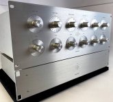
One of the keys to precision setting of the original Audio Palette was custom 59 position switches (60 positions of 6 degrees, minus one for a rotation stop).
The main one I have found with 6 degree indexing is a Seiden unit. But these are stupidly expensive. The 74002 is a 58 position two deck 74001 is a single deck. The quote I got from Seiden was around $250 each. Even if you just did the equalizer that would be $1500 for six dual deck switches. Add to that a further double for the output level and two single for input level, and you are looking at $2k plus for the rotary switches.
There is a 47 position Elma (A47-SERB2-THT is the two deck). That is also 6 degree indexing minus three for rotation stop. But that is a similar price to the Seiden. At least these come with an integral circuit board, so addition of the correct resistors is straightforward.
And a 30 position TKD unit 2R30 and 1R30, but again the same sort of price.
It is only when you get down to 24 position switches that prices become sane.
It is these considerations, I'm fairly confident, that led to using linear pots in the Palette Preamp instead.
Yeah - I considered the relay route - then almost instantly parked the concept because of the cost of the number of relays!
I have thought about whether there is a modification of an R/2R ladder attenuator, where the number of positions is 2^N where N is the number of relays. Kind of like this http://www.vaneijndhoven.net/jos/switchr/design.html
So 6 relays would address 64 values. I need to off-shelve that idea.
But I like the boost/cut switch idea, which seems to be worth trying as a further concept.
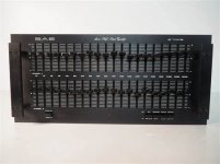
The SAE 2700b
1/2 octave - 20 bands per channel
8 transistors per channel, class A, 24 volt rails, could drive a 600 ohm load.
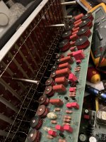
20 inductors per channel- only built for 2 years 76/77 when the gyrator parametrics took over the market - and were cheaper to build. Unit was tall - 5U with long travel 10k Alps pots. Other than the Cello probably the most expensive EQ to build. Top 5 bandpass filters used polystyrene caps, the next 10 were polyester, and the bottom 5 bands were tantalum.
Replaced all the transistors, carbon film resistors, ceramic and tantalum caps with Dale resistors, Wima FKP, and highest voltage 3% Panasonic polypropylene, Belleson +/- 24 volt regulators, Quaismodo snubbed soft recovery diodes, bigger filter caps
1/2 octave - 20 bands per channel
8 transistors per channel, class A, 24 volt rails, could drive a 600 ohm load.
20 inductors per channel- only built for 2 years 76/77 when the gyrator parametrics took over the market - and were cheaper to build. Unit was tall - 5U with long travel 10k Alps pots. Other than the Cello probably the most expensive EQ to build. Top 5 bandpass filters used polystyrene caps, the next 10 were polyester, and the bottom 5 bands were tantalum.
Replaced all the transistors, carbon film resistors, ceramic and tantalum caps with Dale resistors, Wima FKP, and highest voltage 3% Panasonic polypropylene, Belleson +/- 24 volt regulators, Quaismodo snubbed soft recovery diodes, bigger filter caps
Attachments
Last edited:
Here's an idea. Back in the late 70's I built a preamp using discrete opamps. IC's at that time were limited to truly awful performance like the 741.
The problem was that I decided to use a switched volume control, and the only show in town was 12 positions. So I used a flip flop to fire a relay. The idea being that on power up it would be in a low volume range. Turning the control to zero fired the flip flop and it switched to the high volume range. Back to zero and it would be back in the low volume range.
Something around this idea might work for boost/cut switching.
Hi! I‘m lurking and observing this theead with great interest…
Now, this impossible/unpayable switch problem… makes me think of cello‘s own, proprietary design. Why not make your own, in a similar fashion as cello did? Couldn’t it even be printed, could be made into a GB? (Don’t know how many are going into this adventure, if you’re more than one, you got your first dozen switches") )
)
Look here, someone’s gone a similar way (for something quite different): https://www.diyaudio.com/community/threads/reed-switch-audio-attenuator.234967/
Now, this impossible/unpayable switch problem… makes me think of cello‘s own, proprietary design. Why not make your own, in a similar fashion as cello did? Couldn’t it even be printed, could be made into a GB? (Don’t know how many are going into this adventure, if you’re more than one, you got your first dozen switches
)Look here, someone’s gone a similar way (for something quite different): https://www.diyaudio.com/community/threads/reed-switch-audio-attenuator.234967/
Very nice, you did a lot of mods to the unit, how does it sound now vs stock? I bet much better.The SAE 2700b
1/2 octave - 20 bands per channel
8 transistors per channel, class A, 24 volt rails, could drive a 600 ohm load.
20 inductors per channel- only built for 2 years 76/77 when the gyrator parametrics took over the market - and were cheaper to build. Unit was tall - 5U with long travel 10k Alps pots. Other than the Cello probably the most expensive EQ to build. Top 5 bandpass filters used polystyrene caps, the next 10 were polyester, and the bottom 5 bands were tantalum.
Replaced all the transistors, carbon film resistors, ceramic and tantalum caps with Dale resistors, Wima FKP, and highest voltage 3% Panasonic polypropylene, Belleson +/- 24 volt regulators, Quaismodo snubbed soft recovery diodes, bigger filter caps
The reed approach is interesting. But one reed for each switch position. So 59 x 2 for each of 6 frequencies = 708 reeds. Plus a stereo attenuator and two mono attenuators = grand total of 944 reeds or north of $1000 on Mouser's 1000 reed price break. Plus the mechanics, circuit boards and resistors.
You are back in Seiden price territory - and doing it yourself.
Have you looked at the construction of the Cello switches? Multiple ball races, custom contact assembly, in fact everything custom other than the resistor string - they are a thing of Swiss watch beauty. Trying to replicate them would be alas a fool's errand.
Me too. I have my interpretation of the Quad Tilt control integrated into my active crossover, and an updated version of the Cello Blend function (Douglas Self's Devinyliser http://www.douglas-self.com/ampins/Paris 2016 devinyliser.ppt ). In fact I have that effective Blend function engaged permanently. Even with CD's there is often a massive amount of ultralow frequencies; I think that that is probably air conditioning flutter in the recording studio - there is nothing else on the recording at a few Hz. Whatever it is, it is antiphase so the Self circuit just gets rid of it.
Craig
Craig
I've been doing some reverse engineering on the resistor values on the Cello controls. There are enough high resolution images of the web to do this with some modicum of accuracy. Interestingly all the resistors - all 58 of them - are connected in series. The wiper just connects to a single point in the resistor chain.
Considering the lengths that people go to to minimise the number of switched resistors in an attenuator, connecting a chain of resistors in series is somewhat brutal.
Considering the lengths that people go to to minimise the number of switched resistors in an attenuator, connecting a chain of resistors in series is somewhat brutal.
Much more resolving, especially in the bottom end where it has much more detail and control. Use it on 4 of JBL 4350 black plywood clones we have at work - thanks for your pioneering work on power supply noise.Very nice, you did a lot of mods to the unit, how does it sound now vs stock? I bet much better.
- Home
- Source & Line
- Analog Line Level
- Cello Palette Style EQ Design (was High End Tone Control)...