Hannes,
where did you learn that theory? In some Taliban school? The amp is already heavily overcompensated and mudded by a huge amount of capacitors and whatever clamps in the signal path so you don`t have much bandwidth left to use. Commercially you can call this what you like but technically it`s just garbage, which would make Jean Hiraga commit suicide within minutes.
where did you learn that theory? In some Taliban school? The amp is already heavily overcompensated and mudded by a huge amount of capacitors and whatever clamps in the signal path so you don`t have much bandwidth left to use. Commercially you can call this what you like but technically it`s just garbage, which would make Jean Hiraga commit suicide within minutes.
Bad weather in sweden, eh?
I don't know the Taliban schools you're attending, but if they do Bode-analysis then you wouldn't have posted your last, err, comment.
I try to keep close to the original, therefore I try to go for the same stability margins.
I'm sorry for the harsh words, but if you cannot explain what you meant by 'Hitachis are bad for voltage amplification' some posts ago, then you probably also cannot explain the reasoning behind your last claims. I remember in the original thread you also claimed this and your explanation was just 'it's wrong just think'.
Sorry, but this is kindergarten-level of discussion.
Lumba, cool down. This is all about fun.
Have fun, Hannes
Hannes,
yes, I`m still upset because you make a lot of nonsensical statements and we are unable to reach a minimum level of agreeing to conduct meaningful discussions.
Genuine Hitachi 2SD669/2SB649 are fine indeed when used in current stages, high Imax and Cob.
Voltage amplification devices are high voltage/video types (from Sanyo, also Toshiba or Hitachi) have very different chip design handling large voltage swings superbly and linearly (which is not an easy task) at low currents (Imax 50-100mA), high maximum operating frequency (400MHz) and slew-rate, low Cob (2pF).
No?
Both internal and external capacitances always deteriorate the sound in any location therefore have to be avoided or kept low at all costs. The Miller capacitance is extremely harmful. For low distortion we need high bandwidth, fast devices with small Cob. No compensation for low capacitances, just low capacitances.
I cannot stand the way of thinking this design represents.
I constantly have the impression you talk about things you're not the expert you claim to be.
Otherwise I can just say, sorry, you're right, we're not going to find agreement.
The way you 'argue' this just isn't possible. You didn't even suggest an alternative part.
Please, I would appreciate greatly if you would stop posting in this thread, thank you.
Have a nice day, Hannes
Otherwise I can just say, sorry, you're right, we're not going to find agreement.
The way you 'argue' this just isn't possible. You didn't even suggest an alternative part.
Please, I would appreciate greatly if you would stop posting in this thread, thank you.
Have a nice day, Hannes
Lumba, nice to get some constructive input!
It's just a shame that you put the amp so easily at risc of oscillation. I know some of the parts and they're low Cob parts (~2pF), so they have a much larger bandwidth and will make a reworking of the whole frequency compensation necessary.*
But I've said that already before. For those willing to experiment - that also have a bit of equipment - that's fine. My pcb also has this option in case I want to play.
Lumba, I know you don't care about this. You think the amp's overcompensated, but you never explained. I judge from this that you don't know much about frequency compensation. And exactly therefore I suggest the 27pF Hitachi part which should work right out of the box for everybody.
Have fun, Hannes
PS: anyway thanks for the list, might come handy some time. So I don't have to search the forum for the usual suggestions myself
*further you don't need the bandwidth as the output can't handle it anyway. The result is just that you burn the additional bandwidth with compensation. Only benefit left is then the more linear capacitance of the added caps (instead of non-linear bjt Cob).
Power supply
The real thing used a huge high-current choke which is not only expensive, but also emits a huge magnetic field (so keep it far away!).
I will go for a voltage regulated power supply using LT1083 voltage regulators with 10000uF before and after the regulator (the original had 8200uF after the choke).
If you're interested in this as well, I posted a note in the group buy section
http://www.diyaudio.com/forums/showthread.php?s=&threadid=124346
Have fun, Hannes
A few comments
This product developed from the original Performance amplifier. The circuit shown was the input and driver stage for that amp. Output stage used 20 outputs per channel. Input / driver stage sounded so good that Cello introduced it as a separate product.
From later Performance schematics (1996):
2K between C23 & R23 (with ferrite beads on leads)
R23=499K
R44=2M
R60=604
R33=340
2200pf compensation E to C of Q26
R28,29=4.99K
C3,4=2200pf
R26,27=133K
R24,25=10K
Used FDH333 (low capacitance diodes)for D12,13
R1,2=20K
Q14=TIP122(Darlington by the way)
Q15=TIP127
MPD400 diodes across BC junction of Q14,15
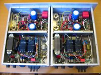
Attached image is a pcb copied from a Cello Encore power amp:
Do you have another side image?

- Status
- This old topic is closed. If you want to reopen this topic, contact a moderator using the "Report Post" button.
- Home
- Amplifiers
- Solid State
- Cello Encore 20th Anniversary Edition