a little more about caps and Timbre {tone}
sba , and other interested readers, see comments I have added after ----> inside the quote box below.
I'll reply to more of your other Posts' matters next time sba, as all my time is up here now unfortunately.
sba , and other interested readers, see comments I have added after ----> inside the quote box below.
sba said:[B
Bypassing capacitors is a little like blending watercolors....
With capacitors, the signature of the base cap can be brightened, softened, darkened or lightened with the addition of the appropriate choice of bypass capacitor. The "perfect" tonal balance can only be determined by ear.
----> Yes, only by ear, but sometimes "perfect" {as defined by the listener} will not be achieved, but only a selection of trade-offs, or worse --> muddiness !
This endeavour is for patient experimenters who have a lot of time, and perhaps money as it may not always work well with cheap caps.
____________________________________________________
Classically, bypassing a capacitor means paralleling a very small cap (0.5% to 1% of the base cap) to improve the effective high frequency performance of the base cap. While this works to a point, the problem with simple bypassing it that it tends to sound a little discontinuous, with the large cap dominating the signature at the low end while the bypass cap dominates the upper extreme.
----> Yes .
____________________________________________________
Cascade Bypassing (or simply "Cascading") is a bypassing method that yields the best and most homogeneous sounding combination of capacitance. Cascading is essentially paralleling smaller and smaller capacitors of increasing voltage to reach the target value. We usually suggest a cascade of 5% to 25% steps,
----> Yes .
____________________________________________________
with each smaller cap having a higher voltage rating.
----> The higher voltage rating is not necessary because the Voltage across the paralled cascaded bundle of caps will be determined by the Reactance of the largest value cap, and that cap must be of sufficient rating for the maximum low frequency signal voltage that will be applied.
All the smaller caps must be not less than the voltage rating of the largest cap.
It is usually co-incidence that smaller caps have higher voltage ratings, and this is because most Manufacturers use a limited number of case sizes {for potted Radial configuration caps} and seem to prefer to fill the cases. Thus they use thicker dielectrics for the lower value caps, and thicker dielectrics permit higher voltage ratings.
Also, in various Industrial applications etc ... {Industry ; Medical ; Military ; Aerospace ; are the major cutomers of cap manufacturers, not Audio !}, it is often the case that small value caps are needed in high voltage ratings more often than large value caps.
____________________________________________________
Cascading sounds better than simple bypassing because it yields an overall homogeneity to the sound of the equivalent capacitor
----> It can yield an overall homogenity, but do keep in mind the first point I made above .
____________________________________________________
Examples of Cascade Bypassing are:
100.0µF = 100µF 100V + 5.0µF 225V +1.0µF 625V (=106µF, within 10% of 100µF)
----> 100uF + 5uF is NOT within the + 25% limit this author specified above, nor is the next example , of 10uF + 1uF + 0.1uF, nor is the 3.0uF + 0.22uF part of that example.
All those are examples of the basic bypassing, which that author has advised against, above ! , and so do I for "homogeneity", unless one is very lucky !!
11µF = 10.0µF 200V + 1.0µF 600V + 0.10µF 800V
5.0µF = 4.0µF 200V + 1.00µF 600V + 0.10µF 800V
3.3µF = 3.0µF 225V + 0.22µF 625V + 0.10µF 800V
----> 4uF + 1uF is a +25% {omit the 0.1uF cap}, but I would prefer closer values for greater likelihood of "homogeneity" {is that really how such word is spelt ?}, eg: 2.7uF + 2.2uF is close enough to 5uF for almost all loudspeaker cross-over applications.
Measure the caps you buy and combine with regard to the differences between their measured values - their Tolerances.
____________________________________________________
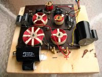
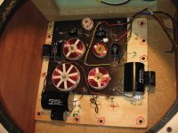
I wonder if Celestion was sort of "cascade bypassing" here at the bottom of the board, mounting a little 6uf 50v on top of the larger 24uf 25v cap.....or just simply assembling a 30uf total?
----> Years ago no manufactures gave any thought to this Cascading idea, and most don't today either, perhaps only a few of the very high priced brands, or highest priced models from a manufacturer of several price/quality ranges.
____________________________________________________
[/B]
I'll reply to more of your other Posts' matters next time sba, as all my time is up here now unfortunately.
clarification about caps' usages, and more about Voltages
First I think I should write one point again for better explanation.
I wrote :-
{Industry ; Medical ; Military ; Aerospace ; are the major customers of cap manufacturers, not Audio !}
Capacitors are used in :- various Industrial applications ; Consumer Electrical and Electronic equipment {including general purpose audio equipment} ; Medical, Military, and Aerospace equipment .
All are manufactured in much larger quantities than are specialist Hi-Fi products.
Yes, there are a few manufacturers of caps, and some other passive components, specifically for specialist Audio.
The specific Voltage ratings they manufacture at are usually the same as the currently accepted Standard Voltages that most other cap manufacturers adhere to.
There are various different voltages found in audio electronic equipment, but in most passive loudspeaker cross-overs only fairly low voltages are ever encountered.
The thicker Dielectric used in a 250 volts rated cap is stressed less when subject to 50 volts than the thinner dielectric is in a 100 volt cap, and this can cause an audible difference, and particually so if the cap is not very tightly wound, or securely potted in a non-resonant compound, as it is then some-what Microphonic.
How much voltage stress do caps encounter in passive crossovers, well multiply your amplifier's maximum power output rating {as specified for the nominal impedance of the speaker load you have connected to it} by the impedance of your loudspeakers, then take the square root of that number, that is the voltage.
Yes, impedance varies across the frequency bandwidth of most loudspeakers, and can be 4 or 5 times the nominal impedance in 2 or 3 regions of the bandwidth, but remember, the amplifier will deliver less power into high impedances than it will into low impedances, thus there will be no significantly higher voltages found.
Examples :-
a 200watt into 8ohm load rated amplifier can deliver 40 volts .
a 50watt into 8ohm rated load amplifier can deliver 20 volts .
a 100watt into 4ohm rated load amplifier can deliver 20 volts .
Thus one would have to use a very high power amp to deliver even 50 volts, hence a 100 volt rated cap is sufficient, AND, is quite safe even if the amp goes faulty and produces DC on its outputs, because the Supply Voltage Rails in all but the very highest power audio amps are less than 100 volts.
More important than Voltage rating is how well the cap is made - tightly wound and securely potted so as to be minimally microphonic.
Using a thicker dielectric does assist to dampen vibration with-in the cap, thus probably why some of the specialist loudspeaker cross-over purpose caps use the 250volt rated dielectric, but it still must be wound tightly or potted securely if to be of audible benefit.
Some even make a 400volt with thicker again dielectric, but to hear the advantage of such over a 250volt rated cap of same quality of manufacture one would need to use very low distortion drivers in a very low resonant enclosure and be driving those loudspeakers very hard !
The 400volt and 630volt rated audio caps are better used inside amps where there are high voltages, such as in tube amps.
The older era loudspeakers used mostly 50 volt rated caps, and those caps were rarely voltage damaged.
The 25volt rated caps used in the oldest Celestion 66s in the tweeter filter of their cross-over are higher voltage than would ever be presented to the 66s in normal use, those tweeters would blow if one's amp was pushed to deliver 25volts in the treble.
But, I wouldn't use 25volt caps in the bass filter, AND, do not drive the old type treble filters hard when testing if the bass and midrange filters are Open {that is with the bass and mid drivers not connected}.
If testing with drivers disconnected, always connect 10watt rated resistors in their place.
The resistors will get hot before high voltage levels are reached.
Touch the resistors whilst testing, and reduce power drive if more than warm.
Cheap 10watt wirewounds are OK for testing, expensive non-inductives are not needed because the drivers they are substituting for are themselves inductive .
Use resistor values the same as or a little higer than the measured DC resistance of the driver.
Example :- for a 6 ohm DC resistance driver, use 6.8 or 7.5 or 8.2 ohm resistor.
The driver's impedance will always be larger than its DC measured value.
the paper-in-oil caps
Yes, you can use those caps together in a parallel bundle.
I will describe how you can attempt to re-condition them to hopefully reduce their leakage if you want to ... ?
Then use new poly caps in the other location in the treble filter, and those will prevent any DC offset from your amp from leaking through the older caps to the tweeters.
sba said:
So, then...Would you extend the "use the same dielectric" recommendation to the entire treble portion of the crossover? For example, four of the Eries have values that are near 4uf ( 3.9 / 3.9 / 4.0 / 4.2 ). Would you recommend using them solo in the 4uf location, while placing new polys in the 6uf location? Or just use polys throughout?
Scott / sba
Yes, you can use those caps together in a parallel bundle.
I will describe how you can attempt to re-condition them to hopefully reduce their leakage if you want to ... ?
Then use new poly caps in the other location in the treble filter, and those will prevent any DC offset from your amp from leaking through the older caps to the tweeters.
What I intended
A bit more time available, thus :-
What I meant in my last Post, is that all the paper-in-oils you can try to recondition.
Some may reduce in leakage of charge sufficiently to return to their original nominal values.
Any such can then be used in parallel in one or other of the Treble Filter cap locations.
New poly caps can be used in the other cap location in the treble filter so that if any significant DC offset from your amp, it will not reach the HF2000 tweeter, as the poly caps will not leak.
I can describe to you how to attempt to re-condition the paper-in-oils, and how to then test them for charge leakage.
Similarly you can test the new poly caps for charge leakage if you want to be sure.
I test almost everything I use !
For reconditioning you may only need to buy two 10watt resistors of the type and values described at the end of my long Post #142 above.
Do you want to try this ?
Re: clarification about caps' usages, and more about Voltages
Seems I've misread something, as I can't see any 25volt rated caps on your list sba, but this information can stay posted in case any other readers have 25volt rated caps in their cross-overs !
25 volts could be exceeded in bass, and some types of mid-range, filters because capacitive reactance is higher at lower frequencies, and thus larger voltages will appear across the caps because there are almost always larger Signal voltages present in Music at bass and midrange frequencies than at treble frequencies.
alan-1-b said:
The 25volt rated caps used in the oldest Celestion 66s in the tweeter filter of their cross-over are higher voltage than would ever be presented to the 66s in normal use, those tweeters would blow if one's amp was pushed to deliver 25volts in the treble.
But, I wouldn't use 25volt caps in the bass filter, AND, do not drive the old type treble filters hard when testing if the bass and midrange filters are Open {that is with the bass and mid drivers not connected}.
Seems I've misread something, as I can't see any 25volt rated caps on your list sba, but this information can stay posted in case any other readers have 25volt rated caps in their cross-overs !
25 volts could be exceeded in bass, and some types of mid-range, filters because capacitive reactance is higher at lower frequencies, and thus larger voltages will appear across the caps because there are almost always larger Signal voltages present in Music at bass and midrange frequencies than at treble frequencies.
"Seems I've misread something, as I can't see any 25volt rated caps on your list sba, but this information can stay posted in case any other readers have 25volt rated caps in their cross-overs !
25 volts could be exceeded in bass, and some types of mid-range, filters because capacitive reactance is higher at lower frequencies, and thus larger voltages will appear across the caps because there are almost always larger Signal voltages present in Music at bass and midrange frequencies than at treble frequencies."
You're correct....three of my speakers have 25 volt caps (the midrange 24uf red-colored CCL caps).
**********************************
"....paper-in-oils you can try to recondition. Some may reduce in leakage of charge sufficiently to return to their original nominal values. Any such can then be used in parallel in one or other of the Treble Filter cap locations."
Since I have four paper-in-oil caps whose measured values are very close to 4uf (a single cap for each 4uf treble location on all four crossovers) , should we skip the reconditioning process that may move the values away from 4uf ?
***
"New poly caps can be used in the other cap location in the treble filter so that if any significant DC offset from your amp, it will not reach the HF2000 tweeter, as the poly caps will not leak."
okay....for the 6uf location then.
***
"I can describe to you how to attempt to re-condition the paper-in-oils, and how to then test them for charge leakage.....For reconditioning you may only need to buy two 10watt resistors of the type and values described at the end of my long Post #142 above......Do you want to try this ? "
It depends on what you think about the above situation with the 4uf caps. Also, do you think that there will be an audible benefit by using the paper-in-oil caps in one of the two treble locations (instead of using the poly caps in both treble locations)?
sba
The caps arrived....but not what I thought I had ordered. I was expecting 68uf caps for the 72 uf location (I know I had considered the 68+4 combination while looking at one of those web stores), but I must have ordered 62 + 10uf from Solen (confused as I was).
So here's what I have:
[ All the Solen caps measured an ESR of 0.03 to 0.04 ohms @ 100 khz ]
********************
for the two 72uf locations--
Solen 62uf / 400v (my readings= seven caps @ 61.15uf / one cap @ 61.30)
&
Solen 10uf / 250v (my readings= four caps @ 10.10uf / four caps @ 10.15uf)
********************
for the 24uf mid location--
Solen 15uf / 250v (my readings= three caps @ 14.60uf / one cap @ 14.70)
&
Solen 10uf / 250v (my readings= three caps @ 9.80uf / one cap @ 10.05)
********************
for the two 4uf locations (treble & mid)--
Solen 3.9uf / 250v (my readings= seven caps @ 3.9 uf / one cap @ 3.85)
********************
for the 6uf treble location--
need to buy four caps
********************
Is this workable?
thanks,
sba
qualifying replies
Look inside the Quote box for comments, as after ---->
I have some ideas for your non-similar size parallelings.
If you can find, read about Time Constants - which are the product of multipling Capacitance by Resistance :- R x C = the TC.
If the TCs can be got in close to for the equvalent sections of each of two x-overs, then both loudspeakers will be crossing over at close to the same frequencies.
I will post more about this next week.
Look inside the Quote box for comments, as after ---->
sba said:
You're correct....three of my speakers have 25 volt caps (the midrange 24uf red-colored CCL caps).
----> Hah, I thought I'd seen 25volts somewhere !
I probably didn't see again as those are Electrolytics and I was looking for the paper-in-oils for possible reconditioning.
{I will write such caps as PIOs in future}
25volts in that location is sailing a bit close to the wind as there is a lot of signal energy in the 250 Hz <--> 1 kHz region where that cap has significant reactance and not a very low impedance parallel bypass from the bass section till the lower frequencies.
But, such will not be a problem with a new higher voltage polycap in there.
****************************************************
"....paper-in-oils you can try to recondition. Some may reduce in leakage of charge sufficiently to return to their original nominal values. Any such can then be used in parallel in one or other of the Treble Filter cap locations."
Since I have four paper-in-oil caps whose measured values are very close to 4uf (a single cap for each 4uf treble location on all four crossovers) , should we skip the reconditioning process that may move the values away from 4uf ?
----> No, because these are NOT actually approximately 4uF caps.
What they are is 2uF leaky caps !
The cap meter probably measures by charging the cap up and calculating the capacitance from the time it takes to charge to a specific voltage through a specific resistance, BUT when the cap is leaking charge it will take longer to charge up to the required voltage, thus the meter thinks it is charging a larger cap.
Also, there is DC capacitance, which is related to the quantity of charge the cap can store, and there is AC capacitance, which is related to the impedance of the cap at alternating signal frequencies.
In an ideal capacitor both these have the same value in uF, but in real capacitors they are not quite equal in most good quality caps, and not so near equal in caps with degrees of charge leakage such as all electrolytics.
That meter does not know the AC capacitance unless it can measure a specific impedance at a specific frequency.
Some meters can do this, usually the types that measure Inductance, and if they have a capacitance function also then maybe it does measure at AC.
Look at data about LCR type meters - meters that are designed to measure Inductance , Capacitance, and Resistance, as distinct from Multimeters which measure via current through an internal resistor and voltage drop across that resistor.
****************************************************
"New poly caps can be used in the other cap location in the treble filter so that if any significant DC offset from your amp, it will not reach the HF2000 tweeter, as the poly caps will not leak."
okay....for the 6uf location then.
----> You can try, see below
****************************************************
"I can describe to you how to attempt to re-condition the paper-in-oils, and how to then test them for charge leakage.....For reconditioning you may only need to buy two 10watt resistors of the type and values described at the end of my long Post #142 above......Do you want to try this ? "
It depends on what you think about the above situation with the 4uf caps. Also, do you think that there will be an audible benefit by using the paper-in-oil caps in one of the two treble locations (instead of using the poly caps in both treble locations)?
----> You have 5 of 2uF PIOs, and 4 of 1.5uF PIOs, thus if all the 1.5s will recondition, and at least 3 of the 2uFs then you will have two sets of 6uF.
This is only worth doing if they will recondition to within 20% of their nominal value, and preferably within 10%, but even then you may have as high as 6.6uF.
It will take the time of a period with each cap series connected to a 10watt 6.8 ohm {or 7.5 or 8.2 or 10 ohm Maximum} resistor, and that series connected pair connected to one channel of your amp and left with signal {pink noise or white noise or fairly dense and repetative music programme} through it overnight, at least 12 hours, though 18 to 24 hrs may give better result.
You could connect up two pairs at a time, one to each channel of your amp.
I would try it simply out of curiosity, but you decide what your time is worth.
As for audible benefit, that is for the listener to decide.
Perhaps make up one set of x-overs with new 6.2uF Solens {or 6uF with 3uF parallel pair} and listen in your Woodys, then as you will have some memory of the original sound of the old x-overs, decide whether to attempt recondition of caps for the other set of x-overs.
Alan.
sba
I have some ideas for your non-similar size parallelings.
If you can find, read about Time Constants - which are the product of multipling Capacitance by Resistance :- R x C = the TC.
If the TCs can be got in close to for the equvalent sections of each of two x-overs, then both loudspeakers will be crossing over at close to the same frequencies.
I will post more about this next week.
Alan,
You really know your stuff !
Due to time constraints, I'm going to install poly caps throughout the crossovers...though I think it would be fun to try the PIO cap rejuvenation experiment....maybe another time.
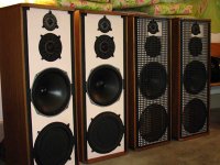
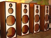
A lot of other stuff has been eating away at the available hours for this project. In order to get all four speakers looking similar, the fronts received a coat of primer and two coats of beige paint. ( So now I guess all four speakers can be called blondies.) Prior to that, the vertical, recessed channels for the grilles had to be cleared of deteriorating foam tape and adhesive, and then painted with black latex paint. And the grilles, once stripped of fabric and glue, were also painted with black latex paint. Scratches on the cabinets were also touched-up. Finally, because of the crossover modification, the back of the cabinets ended up with 2 coats of brown latex paint.
After examining the original crossover location behind the woofer, I felt that there would be insufficient room for a modified board with larger caps at that location. But there's enough room lower down, behind the ABR. The original speaker posts (worthless actually--accept max 20 gauge wire--I always cursed when trying to attach wire to those posts) and their small 3"x4" mounting board must first be removed. They can be removed by hammering the boards into the cabinet from the outside, and then chiseling off any glue on the inside in order to make the surface smooth.
And here’s my recipe for a modified crossover board, which places the original board on top of a larger piece of plywood:
Cut an 11"x11" by 1/2" thick plywood board, which, following the above mentioned removal procedure, will sit flushly against the back of the cabinet and should be placed snugly into the upper left hand corner of the ABR compartment. (The back of the new plywood board should be painted; hence, my full paint job on the back of the cabinet.) Install some new speaker posts directly into the new plywood board (but slightly below the original locations). To accommodate both the speaker posts and the installation of the large 72uf caps, rotate the original crossover board 90 degrees to the right, and screw it into the plywood, using some spacers to float the board slightly above the plywood. The original board should be placed flush with the top of the new plywood, should have about 1” of plywood margin on the left, and should have larger plywood margins on the bottom and right. Fit the caps into place (the larger caps will sit on the plywood margins), secure the caps with with an adhesive (such as RTV silicone, or some other thick & tacky adhesive). When the adhesive is dry, solder the connections. Install the new board into the cabinet using 1” wood screws
This setup also necessitates soldering longer wires to all the drivers.
*******************
I’ll be out of town for a while; but, when I return, I'll post some photos. I’ll have more questions for you, too. I'll also try to get one pair of crossovers installed and hear how they sound.
Sba
You really know your stuff !
Due to time constraints, I'm going to install poly caps throughout the crossovers...though I think it would be fun to try the PIO cap rejuvenation experiment....maybe another time.
A lot of other stuff has been eating away at the available hours for this project. In order to get all four speakers looking similar, the fronts received a coat of primer and two coats of beige paint. ( So now I guess all four speakers can be called blondies.) Prior to that, the vertical, recessed channels for the grilles had to be cleared of deteriorating foam tape and adhesive, and then painted with black latex paint. And the grilles, once stripped of fabric and glue, were also painted with black latex paint. Scratches on the cabinets were also touched-up. Finally, because of the crossover modification, the back of the cabinets ended up with 2 coats of brown latex paint.
After examining the original crossover location behind the woofer, I felt that there would be insufficient room for a modified board with larger caps at that location. But there's enough room lower down, behind the ABR. The original speaker posts (worthless actually--accept max 20 gauge wire--I always cursed when trying to attach wire to those posts) and their small 3"x4" mounting board must first be removed. They can be removed by hammering the boards into the cabinet from the outside, and then chiseling off any glue on the inside in order to make the surface smooth.
And here’s my recipe for a modified crossover board, which places the original board on top of a larger piece of plywood:
Cut an 11"x11" by 1/2" thick plywood board, which, following the above mentioned removal procedure, will sit flushly against the back of the cabinet and should be placed snugly into the upper left hand corner of the ABR compartment. (The back of the new plywood board should be painted; hence, my full paint job on the back of the cabinet.) Install some new speaker posts directly into the new plywood board (but slightly below the original locations). To accommodate both the speaker posts and the installation of the large 72uf caps, rotate the original crossover board 90 degrees to the right, and screw it into the plywood, using some spacers to float the board slightly above the plywood. The original board should be placed flush with the top of the new plywood, should have about 1” of plywood margin on the left, and should have larger plywood margins on the bottom and right. Fit the caps into place (the larger caps will sit on the plywood margins), secure the caps with with an adhesive (such as RTV silicone, or some other thick & tacky adhesive). When the adhesive is dry, solder the connections. Install the new board into the cabinet using 1” wood screws
This setup also necessitates soldering longer wires to all the drivers.
*******************
I’ll be out of town for a while; but, when I return, I'll post some photos. I’ll have more questions for you, too. I'll also try to get one pair of crossovers installed and hear how they sound.
Sba
I've only just stumbled upon this thread. I'm delighted to have found some other Celestion 66 owners discussing these speakers, especially since there is so little information about them available. I recently acquired a pair of the final series 66s (I don't mean the 662 which is really a different speaker), in other words I have the ones with the PCB crossovers.
At first I was a little bit sad to discover I had PCB crossovers but I've persuaded myself that they probably aren't THAT much inferior to the hard-wired ones, that I'd probably never be able to tell the difference by listening to them, and that there are probably a lot more important things you can do to improve the sound such as renewing the crossover capacitors and the flimsy internal wiring.
I haven't had time to read all the thread yet - I'll be doing that at the weekend - but I wonder if anyone has yet pointed out another difference with the final series 66s - they they have a much larger dust cap at the centre of the woofer than the earlier versions? This may be a useful guide as to whether the speakers have PCB or hard-wired crossovers without opening them up, if you were looking at a pair of 66s with a view to buying them.
As luck would have it I have the official Celestion circuit diagrams for both the hard-wired crossovers and the PCB crossovers. (From memory, there is one small difference between them.) Would anyone find it helpful if I were to post them?
I also have a question on the mid-range speakers, which after all is where this thread started. When I got my 66s one of the mid-range units had what looked like a rubber band lying unattached to anything behind the speaker's little metal grill. I was afraid to touch these units so I gave them to Wilmslow Audio to have a look at. They said they'd put the ring back in place but on checking the other unit they'd found it was completely absent - but not to worry about it because it didn't seem to make any difference.
Does anyone know what this rubber or silicone ring does, whether I should worry about it and whether it's possible to get a replacement?
Meanhwile, I'm looking forward to reading the rest of the thread.
Hi everyone,
Well...the speakers sound very good with the new poly caps installed, and it really seems to bring out both the good and the bad in the recordings. My mediocre recordings sound even more mediocre; while those recordings that were well-made and engineered, sound more detailed and impressive. Overall, it's a wonderful improvement, and I really have to thank Alan for recommending the cap replacement, and then leading me through it.
**************
One thing that I wish I hadn't done previously, was to compress a small portion of my itunes music library files beyond the "lossless" level. I don't recall noticing any difference when I did those compressions, but the differences (compared to the original cds) are apparent now--probably because of the crossover improvements, and because I'm listening critically now, and at a louder levels than before (I'm more confident in pushing the speakers, knowing that the cap replacement has brought the crossovers very close to spec).
I've also discovered in all this that my 40gb ipod--though I rarely use it indoors (it's primarily for the car)-- is a poorer sounding music source than the sound card attached to my laptop. (Same exact music files on both...it must be something about the DACs.)
**************
Do you have the top of tower pair standing in the same orientation as the lower pair, or , do you have the upper pair upside-down ? One orientation will give a different sound to the other, in both treble and bass response, and some other audible aspects.....Which orientation do you prefer ?
Originally, I had the towers in two corners of the room, about 17 ft apart, because that was the only available space for them at the time. But, at louder levels, the bass was overpowering and unacceptable. In fact, after that experience, I don't think that these speakers should ever get near a corner. Now they are away from the corners and along a wall, paired about 6 feet apart. The tower arrangement has been replaced with a side-by-side one, with one speaker in each pair inverted. All the speakers are elevated about 2 feet, and are about 2-1/2 feet away from the wall. This setup gives pretty good sound throughout the room, whether one is sitting, or standing and moving about the room.
****************
Was there any conclusion about replacement midranges? After putting the speakers back together, I had an anxiety attack when some "buzzing" appeared on several tracks. I immediately thought it was the "ageing midrange" syndrome. But after investigating further, and hooking up the Dahlquists for comparison, it seems that the buzzing had been caused mostly by caca in some of the recordings themselves--though there might be certain sounds that the mids are not very happy with. I'll have to investigate further.
After that experience, I thought I should make a mental note of possible replacement drivers, since I'm really not equipped with the skills and the tools to rebuild the drivers as tondef has done (and, as time passes, it might be difficult to find a shop that can do it).
Aside from requiring some modifications to the cabinet opening, would the Morel MDM-55 2"dome midrange (mentioned by Alan in an earlier post) be sonically suitable for the 66? Would its specs work with the existing crossovers? ---200w power handling / DCR 6.3 / response 250-6500 hz / Fs 280 hz. Or is there a better choice to keep in mind?
********************
Welcome rwtomkins-- One of my woofers also has the larger dust cap. But in a brief side by side comparison, I didn't notice any sonic differences between the two caps.
cheers,
sba
Hi Everyone, as well
rwtomkins, welcome to our little gathering.
>>>>>
As luck would have it I have the official Celestion circuit diagrams for both the hard-wired crossovers and the PCB crossovers. (From memory, there is one small difference between them.) Would anyone find it helpful if I were to post them?
>>>>>
Please post the official circuit diagrams, as it is yet another data point,
And we will be able to see what changed.
In the meantime I've managed to source another HF2000, in good condition via ebay,
this one measures 4.5R, so that makes be happy. I just need some time to swap it in, and have a good listen.
Now the nights are drawing in, maybe we'll all have more time for indoor activities.
Grahame
Thanks for the welcome, guys. Sba, your 66s and their new crossovers look awesome.
Sba, if you're interested in having your midranges rebuilt, there's a fantastic guy in Essex called Dave Smith aka DK Loudspeakers who can (and does) rebuild just about anything. I spoke to him the other day and he'd just done two pairs of MD-500s. He doesn't believe in the internet (!) but his phone number is 01708 447344.
Grahame, I've scanned the three pages of circuit diagrams and other info on the 66s and now have three nice jpeg images, but I don't know how to post them. If I compress them to the point where I can attach them, I don't think the resolution will be high enough to enable them to be blown up again to the point where you can read them. Any suggestions? Ideally I would probably copy them and paste them into a post but I don't see how I can copy text from a jpeg image.
rwtomkins,
some approaches on images,
1) can you get a readable gif (rather than jpeg) below 102400 bytes to attatch ?
2) Do you have a ISP provided web page / web photo account where you can host the images. Then post a link in you message or use the IMG button in the vBCode section to paste the link in your reply.
3) email the readable images to someone who can do 2)
ignore the FAKE words in the following
FAKE spam4ga FAKE @ FAKE yahoo FAKE . FAKE com SPAM")
some approaches on images,
1) can you get a readable gif (rather than jpeg) below 102400 bytes to attatch ?
2) Do you have a ISP provided web page / web photo account where you can host the images. Then post a link in you message or use the IMG button in the vBCode section to paste the link in your reply.
3) email the readable images to someone who can do 2)
ignore the FAKE words in the following
FAKE spam4ga FAKE @ FAKE yahoo FAKE . FAKE com SPAM
- Status
- This old topic is closed. If you want to reopen this topic, contact a moderator using the "Report Post" button.
- Home
- Loudspeakers
- Multi-Way
- Celestion 66 needs mid-range