Hi Alan (at al).
Well, after much procrastination (and several weeks down-time with a severe cold – my second in 2 months) I have my cross-overs finished. I plugged them into the system this morning and heard ….nothing. Been so long I’d forgotten how to turn my system on – 7 switches not 6. Anyway, it all sounded pretty good but something wasn’t quite right. Voices, which are usually centered between the speakers, seemed to be at the edges; a sign I think of incorrect polarity somewhere and sure enough I had reversed polarity on one of the MF500’s. So all good now. I’m so surprised that there are no hums, buzzes, whispy bits of smoke and/or burning rubber odours! Over the next few weeks I’ll try to voice them using combinations of the resistors you have recommended together with a variety of differing musical types. My resistor default settings at the moment are:
Midrange = 24.5uf capacitor/1.5 ohm R (alternatives 0.51 ohm or 1.0 ohm) and 4uf capacitor/3.9 ohm R (alternatives 2.7 ohm or 3.3 ohm).
Tweeter = 3.6uf and 11uf capacitors with the 0.51 ohm R/30.9 ohm R LPad (alternatives 0.75 ohm or 1.1 ohm and 24.9 ohm or 18.0 ohm or 62 ohm* (*to be used on its own!)
Alan, while convalescing I ordered replacement capacitors for the bass section of my new cross-overs (not wishing to pull the old ones apart). However, I was only able to get 70uf so I have supplemented these with a 4uf capacitor. So, the line-up there is now:
1 x 70 uf capacitor/1.5 ohm R plus 1 x 70 uf capacitor/1.0 ohm R with a 1 x 4uf capacitor/8.2 ohm R. But I think this last resistor was your suggestion if accompanying the existing 2 x 68uf Solens capacitors and the 1 x 8.2uf Solens I was going to take from the tweeter section of the old Xover. Could you advise me further on this please?
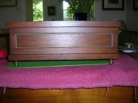
Lastly, thank you for your offer of assistance (Post #1014) to help me build some speaker stands. Unfortunately my wife thinks that 105cm’s is a fine (as in finite) height so, as an alternative, I have built little boxes for the cross-overs that hide under the console that holds all my gear.
Regards to all
Reggie
Well, after much procrastination (and several weeks down-time with a severe cold – my second in 2 months) I have my cross-overs finished. I plugged them into the system this morning and heard ….nothing. Been so long I’d forgotten how to turn my system on – 7 switches not 6. Anyway, it all sounded pretty good but something wasn’t quite right. Voices, which are usually centered between the speakers, seemed to be at the edges; a sign I think of incorrect polarity somewhere and sure enough I had reversed polarity on one of the MF500’s. So all good now. I’m so surprised that there are no hums, buzzes, whispy bits of smoke and/or burning rubber odours! Over the next few weeks I’ll try to voice them using combinations of the resistors you have recommended together with a variety of differing musical types. My resistor default settings at the moment are:
Midrange = 24.5uf capacitor/1.5 ohm R (alternatives 0.51 ohm or 1.0 ohm) and 4uf capacitor/3.9 ohm R (alternatives 2.7 ohm or 3.3 ohm).
Tweeter = 3.6uf and 11uf capacitors with the 0.51 ohm R/30.9 ohm R LPad (alternatives 0.75 ohm or 1.1 ohm and 24.9 ohm or 18.0 ohm or 62 ohm* (*to be used on its own!)
Alan, while convalescing I ordered replacement capacitors for the bass section of my new cross-overs (not wishing to pull the old ones apart). However, I was only able to get 70uf so I have supplemented these with a 4uf capacitor. So, the line-up there is now:
1 x 70 uf capacitor/1.5 ohm R plus 1 x 70 uf capacitor/1.0 ohm R with a 1 x 4uf capacitor/8.2 ohm R. But I think this last resistor was your suggestion if accompanying the existing 2 x 68uf Solens capacitors and the 1 x 8.2uf Solens I was going to take from the tweeter section of the old Xover. Could you advise me further on this please?
Lastly, thank you for your offer of assistance (Post #1014) to help me build some speaker stands. Unfortunately my wife thinks that 105cm’s is a fine (as in finite) height so, as an alternative, I have built little boxes for the cross-overs that hide under the console that holds all my gear.
Regards to all
Reggie
to Reggie above , + about placement of Inductors , + interim to DennyG
G'day Reggie ,
hah , you got your crossovers assembled sooner than I thought you would ,
and thus sooner than I had time to post about Layout and positions for the new large Inductors.
I did post a little in a previous post about positioning these large Inductors ,
but not all I had intended to ... at least not in any Post I have been able to find now , despite too long looking !
***
For all readers - placement of large Inductors for minimal Inductive Coupling:-
I previously advised a minimum of 10.5" x 10.5" board if all crossover has to be on one board.
{ Better is to use two boards:- 11" x 5" for the Woofer filter , and use the old Celestion board for the Midrange and Tweeter filters.}
Alternately use 11" x 10.5" or 10" if all on one board.
The new Woofer filter Inductors are so large they need to be a distance equal to or larger than the Diameter of the 3.5mH distant from each other ,
and larger distance away from all the other Inductors so that their Magnetic Fields do not excessively interact with each other.
Magnetic Field interactions are Inductive Coupling and will reduce the filter's effectiveness ,
because the coupling transfers part of the unwanted electrical signal into the next stage , or into another filter's stage , and thereby into the drivers.
To minimize this coupling:-
Put the new 3.5mH in one corner of the new board.
Put the large 2.2mH Woofer filter Inductor in the adjacent corner along the 11" side ,
{ or the 10.5" minimum side } ,
so both Woofer filter Inductors are on one side of the board.
Put the small 2.2mH Midrange filter Inductor in the corner diagonally opposite to the large 2.2mH Inductor.
Put the 0.14mH Tweeter filter inductor in the corner diagonally opposite to the 3.5mH inductor.
Thus the Tweeter filter's inductor is largest possible distance away from the primary source of bass coupling ,
hence very very little bass will get to the tweeter circuit where it would cause the worst audible effect.
Draw a line diagonally across the board from the 0.14mH inductor to the 3.5mH inductor.
Measure and mark the half-way point between the OUTSIDES of both those inductors along this line -
{ NOT the half-way point between the Centres of these two inductors }.
Stand the 0.34mH Inductor on its edge so it is like a Wheel ,
and place it on the line so that it could be rolled along from 0.14mH to 3.5mH and back.
Put some Silicone sealant on that half-way mark , position the 0.34mH on that in the direction I stated above ,
and tightly tie that inductor to the board with a Nylon cable tie.
Use Nylon , not Plastic , because plastic will stretch and loosen over time , but Nylon will stay tighter.
Do NOT use wire to tie the inductor , because wire being metal will become a Core to the inductor and thereby increase its Inductance.
In the position I have described the 0.34mH inductor will be off-centre away from the other diagonal of the board
from one to the other of the two 2.2mH inductors , and that is good for less Inductive Coupling from those.
Put the Woofer filter capacitors between the two Woofer filter inductors ,
and position them Parallel to each other , and so their axis's points from edge of board to the centre of board.
Put the 24uF Midrange inductor between the 3.5mH and the Midrange 2.2mH , and also axially pointed from edge of board to centre of board.
Put the 3.9uF Midrange cap between the 2.2mH midrange inductor and the 0.14mH , closer to the 2.2mH , and again pointing axially from edge of board to centre of board.
Put the two Tweeter filter capacitors one each side of the 0.14mH and near to it , and pointing axially from edge of board to centre of board.
Stick all those components to the board with Silicone sealant , and tie them tightly through the board with Nylon cable ties ,
but NOT the Resistors.
The resistors are small and light weight , thus do not need to be tied down.
They will dissipate their heat better and thus stay cool when held above the surface of the board.
Their wire end leads are strong enough to hold them above the surface ,
so solder their leads to the capacitors leads and then bend the resistors' leads gently and at a distance not less than half inch from their bodies so as to not stress the connections to their bodies.
Bend through no larger than 90 degree angle of the wire lead.
Make a part circle shape with the wire lead if you need to bend it further to hold the body above the surface of the board.
Basically , make the leads to be legs for the bodies of the resistors.
Reggie ,
if you have positioned some or all of your components differently , you can change some of them if you have used Silicone sealant ,
because it can be cut with a sharp blade.
The inductors need to be as I described , including the 0.34mH positioned like a wheel ,
otherwise you will have a degree of Coupling sufficient to reduce the effectiveness of these expensive components you have bought ,
and thereby a less audibly good crossover than is possible.
The capacitors' positioning is less critical , because there is a lot less Fields' coupling through those than through the inductors.
The bodies of the resistors should not be left touching any other component or surface.
The 70uF + 1 ohm Parallel with 4uF + 8.2 ohm is OK if you have this double pair in the circuit location you drew the capacitors/resistors pairs at in your Schematic in #946 on Page 95 ,
and the 70uF + 1.5 ohm in the other location in that circuit ... are they ?
As you have started with the least attenuation to the tweeter , leave that whilst you are deciding the midrange Series resistance.
If the tweeter sounds too bright , then decrease the 1.5 ohm in midrange to 1 ohm , and to 0.5 ohm if necessary , or even to no resistor there.
Leave the 3.9 ohm in the Midrange filter till you have decided all the others.
Basically , the amount of Series resistance in the Midrange and resistances in the L-Pad around the tweeter need to be chosen to achieve the balance you prefer with the woofer now at higher output.
You may have to increase the resistances in the tweeter L-Pad to achieve this.
After all the above is closest to your preference you can experiment with the resistance to the 4uF in the midrange filter.
This resistor not only changes the upper-midrange/lower treble level , but also changes the Vertical listening axis.
It changes the Vertical axis because it changes the Phase response of the midrange filter.
This is evident in the series of simulated response plots that DennyG has posted recently.
If you are not happy with the integration between mid-dome and tweeter at the listening height you are now restricted to with no loudspeaker stands ,
then decrease from 3.9 ohm to 3.3 ohm , and even to 2.7 ohm if necessary.
If none cause the effect you want , then report here which is closest , or between which two resistances is closest ,
or whether neither the 3.9 or 2.7 is far enough outside the range of 3.9 <--> 3.3 <--> 2.7 .
***
Reggie ,
you seem to have a lot of money to spend , as you bought new caps for the Woofer filter !
Please post here the Brand name and Seller of these 70uF capacitors ,
which I hope are not Electrolytics ... ?
so that other readers can buy those if those are the easiest for them to obtain.
*** *** ***
G'day DennyG ,
there is a lot in your series of plots that requires comment by me to put all into useful perspective.
I will get to that when I have time available.
I attended to Reggie's new crossover first , because he is fine-tuning it now.
To be even more useful it would be good to have similar simulated plots for the HF2000 tweeters ,
but that will be more difficult to do as result of their much larger change of Impedance through the crossover region.
We can do a series for the Woofers to see if any significant differences between using two 72uF versus 68uF + 75uF { or close to 75 as yours is }.
This series could include changes to the resistors ,
but there is a lot more compromise there with the resistors between minimal for filtering of upper midrange versus more for reducing resonances
than is in the midrange filter's options.
Doing a series of simulations for the low-midrange end of the midrange filter will not show much of use unless many plots done ,
including specifically for different frequencies with different Impedances , because of the very large change of Impedance there ,
and it will all be quite complicated to explain.
I will only attempt such if you are not happy with the integration between mid-dome and woofer after you have all else close to optimum ...
... for which yet we need new measured Frequency response and Impedance plots for both your mismatched HF2000s .
Last edited:
Hi Alan (et al).
Yes, very quick to complete the crossovers (2 months??). Plus 3 years of planning. Lessons learned: (i) do not use 12 gauge solid core wire in a crossover (almost impossible to get silver solder to adhere to it in a reasonable time (ii) don’t twist leads together and then solder them unless you intend to let them stay that way forever (iii) don’t try to reinvent the wheel – although only having one set of speaker wires from the amp to the crossover, I have three sets of wires (woofer, mid and tweeter + and -) from the crossover to the speakers.
Anyway. Despite my initial post expressing my joy at not having any teething problems several matters did come up that left me befuddled. The first was with a crackling sound coming from the right hand speaker followed by the woofer failing. It took a couple of days to find a bad solder joint. The second problem was quite strange. After soldering various resistors in and out of the circuit I was listening one night and the music wouldn’t centre itself. In fact the sound from the left speaker seemed to come from about 6 feet to the left of the speaker. That took a couple more days to discover one lead of the 8.2 ohm resister attached to the 4uf capacitor in the bass circuit had fractured, right up next to the resistor itself. Not having any more 8.2’s I soldered in two x 3.3ohm resistors in series. However, the focus then moved too much toward the right hand speaker so I wired in a 1.5ohm resister in parallel to the 8.2ohm resistor in the right hand crossover to bring it down a bit. My wife says the focus is pretty well centred now but I will order some more 8.2’s. To answer your question Alan yes, I am using the 70uF + 1 ohm Parallel with 4uF + 8.2 ohm and the 70uF + 1.5 ohm in the other location in that circuit. As for the tweeter Lpads I am using the 0.5ohm and 30.9ohm. I’ve found that, for most purposes, it provides me with more treble than before without becoming too obvious. For example in the Wishbone Ash tune “Warrior” to hear that cymbal passage we discussed in a previous post I had to put a cardboard tube to my ear and then put it up to the tweeter. Now, although still not hearing it from my listening position (12 feet from both speakers in a classic V format) if I move to within 4 feet I can hear it. So that’s a db increase to a factor of ????
The new bass capacitors I bought were Obbligato Film in Oil 70uf from DIYHiFi in Hong Kong. Unfortunately, I didn’t read the small print; these things are huge: 13 cms long and more in circumference. They take up a lot of space on the board. The boards I made with the speaker stands in mind so they measure 13” x 10”. Although I didn’t follow the inductor guidelines you specified in your last post I did look at a lot of pictures on the internet and read Troel Gravesen’s guidelines on inductor placement. I have mounted the big 3.45mh coil flat with the 2.2mh coil upright and at a 90 degree angle to it 7cm’s away. The other coils are oriented at 90 degree angles to each other and are spaced across the board.
Some early impressions. Over all, while I’m very happy with the bass (eg more punch with the kick drum and the whack of the snare (?) drum and more musical eg. more definition to something like a plucked bass) and the treble (leaving aside the loss of my high frequency hearing I am pleased with what I do hear with the Hiquphon. Very nice shimmer and decay to cymbal strikes etc. However, I’ve yet to try and fine tune the midrange. What I mean is that, as I understand it, the midrange is where all the voice action occurs so on some songs on some CDs some of the words/lyrics are indistinct. Now that could be because they are badly recorded However, I’ve noticed that with the new crossover I can discern/interpret more of these badly recorded passages than with the old crossover. I’m not sure whether to attribute that to (a) the lack of vibration from an externally mounted crossover (b) higher quality parts (c) changes made by the different architecture you’ve suggested in the crossover frequencies or (d) imagination on my part. Anyway, perhaps Alan you can tell me whether changing the resistor attached to the 4uf cap in the midrange could have an effect on clarity (I’m currently using the 3.9uf)?
I have taken some photographs and will post these when I learn how.
Well, enough for now. Thank you for reading.
Regards
Reggie
The real lesson I learned about silver solder is, don't use it at all! The presumption that the presence of silver in it will increase conductivity is erroneous. What you want is Lead! More specifically tin, lead and copper. Alan will no doubt back me up on this. It has made soldering a joy again, and my joints stronger physically and electrically.
I'm a Ditton 44 man, so shan't comment on the other stuff, other than to say well done!
I'm a Ditton 44 man, so shan't comment on the other stuff, other than to say well done!
Hello Lucas. Yes, I remember now learning a lesson some time ago when I first used lead free soldier. Obviously I forgot what that lesson was. The solder I’m using now is a Mundorf silver/gold. The label tells me its lead and cadmium free and the contents are: S-sn95,5Cu0,7Ag3,8Au. With a 40w iron it melts very quickly on the inductor and capacitor leads (leaving a very neat shiny ball of solder) but using it to attach leads to the 12 guage wire was something else.
Hello DennyG.
Well my equipment for the last 4 years has been Elson Silva (Sydney based – you can read the review on his latest stuff here www.6moons.com/audioreviews/cymer/1.html ) monoblock push/pull valve amps operating in triode; a (second-hand) Cec TL1 Cd transport; an Audio Gd Mk7 dac; a Tram Mk 2 OTL pre-amp and of course the Celestions. The room is our 5.3m x 4.3m formal lounge-room so has a large stuffed couch (upon which I sit to listen) against the long wall facing the equipment, flanked by 2 stuffed chairs and a 2m x 3m Persian rug in the middle. It has shutters on the large front windows and glass framed artworks on every wall. The room and furniture are a constant. The room is not treated.
I don’t really analyse the sound I hear. There’s no AB as such. I play certain Cd’s more than others and have become familiar with them and, of course, I know the Celestions intimately having had them for 36 years. From my point of view there have been two sorts of changes; revolutionary and evolutionary. The two really big fundamental changes in my system have been the Cec which was a huge advance (from the Rega Apollo CD) in everything and the Audio Gd was a huge advance in depth and weight. Other changes have been more incremental. The Tram replaced a Bent Audio passive pre-amp (TAP). Initially there was only a very minor difference between them relating mainly to the “feel” of the music. Later with the addition of the Coleman heater modules for the 45/2A3 valves there was an improvement in clarity from the Tram. Then, at Alan’s suggestion the addition of the resistors and a change from the 34uf to a 24uf capacitor in the midrange of the Celestions wrought another small improvement. (I really cannot give you a better word than improvement. It means I’m hearing a more “alive” “realistic” “clearer “enjoyable” rendition of the music). Some changes I readily admit I cannot hear. I have spent a small fortune on NOS valves that make no apparent difference. Cables, interconnects etc. I have listened to for hours and cannot hear a difference. They might be there but with my ears and on my equipment I cannot hear it. So, with Alan’s crossover I am hearing an incremental change for the good.
I have no idea what my equipment sounds like vis a vis anybody elses (and maybe that’s a really good thing). I feel very happy about how it sounds…but I guess I still strive for that extra bit of realism (which is obtainable with some very fine recordings). Anyway. I’m going to experiment with different resistors in the midrange to see if one is “better” for me than another.
Regards
Reggie
Reply to reggie
Hello reggie,
Thanks for the description. I'm not familiar with any of the components but I don't follow the hi-fi component area until I need to replace something. I agree with you about the importance of CD source components. I remember when I was upgrading my first CD player (a Nakamichi) Meridian had an integrated player and a separate transport & converter and both sounded good but when I borrowed both and listened on my system there was no comparison so I ended up buying the separates and still use them. For the 66s I use a fairly old BX model Rotel integrated player so that is an area I could probably improve on.
I described earlier the 66 sound improvements I heard when adding the resistors and then the next sound improvement with the new caps. I would describe them as revolutionary especially the resistors. The improvement with the caps was more subtle.
I also found significant differences in the resulting sound for various CD/amp interconnects. But I only have one really good interconnect set so that may be the reason. I've had most of my gear for many years. Amps are another component that needs further investigation.
I hope to get back to testing the drivers again and then adjusting the resistors for further improvements.
Good luck and hope you survived the recent Melbourne heat.
Regards
DG
Layout of Posts for ease of reading and following , so as to be able to reply well
G'day Reggie ,
please refer to this Link here in diyaudio:
http://www.diyaudio.com/forums/multi-way/79797-opinions-tweeters-please-8.html#post937264
The above should take you to Page 8 of the Thread titled:
Opinions on tweeters please
which was stated by:
RDV
There I refer you to my Post #74.
Do not necessarily read that post , but look at how the Lay-Out is , and also in my 75 <--> 77 ,
and then please read the Moderator's reply and request in #78 , and my follow-up in #79 ,
and then his instructions to me in #80.
Next you can see my improvement in #87 on Page 9 of that Thread.
I list the above here , because I want you to know that I had very little Computer skills ,
{ and I still have only a few more now }.
It is thus not my intention to be rude , and I hope to not offend you by what I am going to ask ,
however I cannot easily follow your Posts.
My memory is not good for new information , thus to Reply to your Posts I have to re-read them during my replying to find the next bit of information ,
and that is very hard to find because so much is all on long lines and with very little spacing , even when you change Subject some-what.
I can see that you are aware of the function of the ENTER key , because sometimes you do start a new line , but not often enough.
I do NOT know what type of Computer you usually use ,
thus your Posts may look quite neat to you when you type them ,
however on the computers I have access to the way the Posts are changed causes very long lines with new Sentences starting mid-line and continuing into the next line.
I am sorry , but it is taking me too long to follow your information to be able to Reply in the limited amount of time I have available ,
thus I ask you , PLEASE set out your Posts with:
(1)- Each new Sentance starting on a new line ,
(2)- When you change Subject , even a little , please leave a Blank line , and start a new Paragraph.
The above is what I do in my Posts in the hope that interested readers are able to follow what I am stating.
I will now Copy your last Post to me , and Paste it in a new post below here ,
and I will space it in a way I can find the information in readily , so that you have an example of what I mean.
I will then Reply to it.
I apologize if the above may seem offensive to you , as I do not intend any offense.
I am simply trying to maximize efficiency.
Last edited:
Initial Reply to #1023 - report of results by Reggie ; Agreement with LucasAdamson
Here is a Copy and Paste , and a re-setting of the spacings of #1023 :
Hi Alan (et al).
Yes, very quick to complete the crossovers (2 months??).
Plus 3 years of planning.
Lessons learned:
(i) do not use 12 gauge solid core wire in a crossover (almost impossible to get silver solder to adhere to it in a reasonable time
(ii) don’t twist leads together and then solder them unless you intend to let them stay that way forever
(iii) don’t try to reinvent the wheel – although only having one set of speaker wires from the amp to the crossover, I have three sets of wires (woofer, mid and tweeter + and -) from the crossover to the speakers.
Anyway. Despite my initial post expressing my joy at not having any teething problems several matters did come up that left me befuddled.
The first was with a crackling sound coming from the right hand speaker followed by the woofer failing.
It took a couple of days to find a bad solder joint.
The second problem was quite strange. After soldering various resistors in and out of the circuit I was listening one night and the music wouldn’t centre itself.
In fact the sound from the left speaker seemed to come from about 6 feet to the left of the speaker.
That took a couple more days to discover one lead of the 8.2 ohm resister attached to the 4uf capacitor in the bass circuit had fractured, right up next to the resistor itself.
Not having any more 8.2’s I soldered in two x 3.3ohm resistors in series. However, the focus then moved too much toward the right hand speaker so I wired in a 1.5ohm resister in parallel to the 8.2ohm resistor in the right hand crossover to bring it down a bit.
My wife says the focus is pretty well centred now but I will order some more 8.2’s.
To answer your question Alan yes, I am using the 70uF + 1 ohm Parallel with 4uF + 8.2 ohm and the 70uF + 1.5 ohm in the other location in that circuit.
As for the tweeter Lpads I am using the 0.5ohm and 30.9ohm.
I’ve found that, for most purposes, it provides me with more treble than before without becoming too obvious.
For example in the Wishbone Ash tune “Warrior” to hear that cymbal passage we discussed in a previous post I had to put a cardboard tube to my ear and then put it up to the tweeter.
Now, although still not hearing it from my listening position (12 feet from both speakers in a classic V format) if I move to within 4 feet I can hear it.
So that’s a db increase to a factor of ????
The new bass capacitors I bought were Obbligato Film in Oil 70uf from DIYHiFi in Hong Kong.
Unfortunately, I didn’t read the small print; these things are huge: 13 cms long and more in circumference.
They take up a lot of space on the board. The boards I made with the speaker stands in mind so they measure 13” x 10”.
Although I didn’t follow the inductor guidelines you specified in your last post I did look at a lot of pictures on the internet and read Troel Gravesen’s guidelines on inductor placement.
I have mounted the big 3.45mh coil flat with the 2.2mh coil upright and at a 90 degree angle to it 7cm’s away.
The other coils are oriented at 90 degree angles to each other and are spaced across the board.
Some early impressions.
Over all, while I’m very happy with the bass (eg more punch with the kick drum and the whack of the snare (?) drum
and more musical eg. more definition to something like a plucked bass) and the treble (leaving aside the loss of my high frequency hearing I am pleased with what I do hear with the Hiquphon.
Very nice shimmer and decay to cymbal strikes etc.
However, I’ve yet to try and fine tune the midrange.
What I mean is that, as I understand it, the midrange is where all the voice action occurs so on some songs on some CDs some of the words/lyrics are indistinct.
Now that could be because they are badly recorded However, I’ve noticed that with the new crossover I can discern/interpret more of these badly recorded passages than with the old crossover.
I’m not sure whether to attribute that to
(a) the lack of vibration from an externally mounted crossover
(b) higher quality parts
(c) changes made by the different architecture you’ve suggested in the crossover frequencies
or (d) imagination on my part.
Anyway, perhaps Alan you can tell me whether changing the resistor attached to the 4uf cap in the midrange could have an effect on clarity (I’m currently using the 3.9uf)?
I have taken some photographs and will post these when I learn how.
Well, enough for now. Thank you for reading.
Regards
Reggie
*** *** ***
Reggie ,
I don't know how the above re-sets itself for the screen width you have access to ,
but here's hoping ... !
My Replies:
(1)- 12 guage , you stated ...
Those inductors for the woofer section are 14 guage ,
and if you found AWG14 thickness a problem to work with ,
well ... wait till you have to work with AWG12 , if ever !
Basically what is happening is that thick wire is acting as a Heat Sink
and is drawing too much of the Iron's heat away from the point where the solder needs to adhere.
I hope you are soldering as follows:
Place the Tip of the hot iron onto the point on the wires' connection where you want to solder.
Hold it there till the wires' junction is hot.
Keep it there.
With your other hand , touch the end of the solder wire to the hot point of the component leads' junction ,
and hold it there till it melts.
After the melted solder has spread itself , remove the Iron ,
BUT hold firmly the components' leads in place until the solder sets.
If the leads move before the solder has fully set , the joint will be electrically poor ...
{ regardless of Silver and Gold in the solder , etc ... }
If you are close enough to the leads , blow on them - that will cool the solder to faster set ,
so that you are not struggling to hold the leads stable.
If the leads do move , then hold it down , apply the Iron and melt the solder at the junction ,
remove the Iron and hold firmly till the solder sets.
Sorry , it is tedious , but it will not work well otherwise ,
and will render irrelevant the benefits of expensive capacitors , etc ...
Basically , the wire needs to be hot enough for the solder to melt on the wire ,
and not only melt on the tip of the iron.
(2)- the less twisting together of leads the better for solder joints.
Do a short twist only ,
and better is to form a small hook shape at the end of each lead to hold them together and pressure the hooks together tightly with pliers ,
then solder over that hooks' junction.
(3)- Regardless of whatever instructions may have come with the Inductors ,
or that you may have read elsewhere ,
to solder Inductors into circuit with any DIY soldering iron , first scrape the insulating varnish off the ends of the Inductor ends' leads.
Use a sharp blade , or close pliers around the end of the wire and twist to remove a short length of the varnish completely.
Do not expect the hot iron to sufficiently remove the varnish.
That varnish is able to withstand heat - it has to ,
because it is used inside Transformers , etc , where the wire can get very hot !
(4)- The degree of Image Shift you described is result of more than simply one 4uF cap out of circuit with respect to 70uF.
It would require at least about twice that amount of capacitance difference to cause such shift , 10% , and likely require more.
If I have understood you correctly you have 1.5 ohm in Parallel with 8.2 ohm in one channel , and 6.6 ohms in the other ?
That would be 1.5//8.2 = about 1.33 ohm in one channel , and 6.6 ohms in the other.
Again , such amount of resistances in connection with only about 5.7% Nominal of the Total Capacitance would not alone cause such degree of Image Shift ,
and basically you have now set a new imbalance to attempt to correct a different cause of imbalance.
I think there is another problem , and which your remedies are assisting only part of.
Try this:
Remove both 4uF caps and their resistors from both channels of the crossover.
That is , have the 70uF caps and their resistors in circuit only.
Whilst you are doing that , look very carefully around the circuit to see if there are any places where there are Short Circuit and/or Open Circuit connections ...
... including solder joints that set whilst the leads were moving.
Next , listen with only the 70uF caps and their resistors in , with the 4uF caps and their resistors out.
Report the results here.
There is another possible cause of this Image Shift , unrelatated to the caps ,
but to diagnose that I will need to see Plan View photos of BOTH crossovers
so that I can see the exact Lay-Out on each board.
Even if both boards look close to identical lay-out to you , they may not be electrically.
I will explain how that can be after I see the photos ,
because then I can direct you where to look for problems.
(5)- Leave the Tweeter L-Pads as you had them , and also the Midrange resistors ,
until we sort out this Image Shift problem.
(6)- I posted what I thought about those Obbligato caps at point (7) in #902 on Page 91 ,
including their physical size.
OK , you have been determined to try them , and now you have ...
... that is your decision to make , and this is DIY ,
however if you had informed me you did not want to take the old Solens off the Celestion board I would have advised something else for new woofer filter caps , and smaller in physical size.
(7)- Are the 4uF caps in the Woofer filter Obbligato also ? ,
or what brand and type number ?
*** *** ***
I agree with LucasAdamson about not using Silver solder.
Silver solder is designed for use with components that have silver contact areas , and to connect silver or silver plated wire to those points.
The issue is to do with the integrity of the connection.
It is not anything to do with the small degree of silver's conductivity in the solder - so small there as to be irrelevant.
I advise use of 63/37 Tin/Lead solder , and that is Eutectic.
If you cannot obtain 63/37 , then use at least 60/40 Tin/Lead , and which is almost Eutectic.
It is worth the effort to find 63/37 , even if have to pay for Mail Order shipping ,
and relevant to what you have spent on crossover components Reggie , the cost of decent solder is a minor point !
Ideally , I would remove all the Silver solder from the crossovers and re-do with 63/37 ,
however leave it for now Reggie , because there is more disconnecting you may need to do yet to solve this Image Shift problem.
Do NOT mix the existing Silver/Gold solder with any new bought 63/37 at the same joint points.
I have not researched this Mundorf Silver/Gold solder to find whatever claims about it ,
however Cardas did have some useful information about their different formulations of solders.
I posted about Solder earlier in this Thread , or perhaps it was only in another Thread I posted it ... ?
G'day DennyG ,
Do you remember if I posted about types of Solder here ?
I think it may have been in discussion with you and Wayne Swann I posted about the solder types , over a year ago ...
What solder type do you use ?
Last edited:

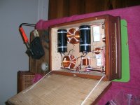
Hi Alan. These are pictures of my crossover(s).
Now I know how to upload them I will do better (closer-up) ones if so desired.
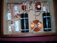
Picture 1 is the best. It shows that my layout is almost an exact translation of my schematic (you have to reverse the image to see it). It is laid out in three parts: woofer, mid and tweeter.
The red wire you see is 12awg solid core copper wire that I also used as the speaker wires.
Reading the wires at the (top) of the box from the left you will find: Tweeter (+)(-) Mid (+)(-) Bass(+)(-) Input (+)(-).
You will see that the input positive wire (2nd from right) goes in at the (top) of the board then underneath and emerges at the (bottom) near the big coil.
I'm sorry about my previous posts. They look fine when I post them. Is this present post better?
I'm away over the next week or so visiting my wife's brother in the country. I hope everyone has a nice break over the (Christian) holiday period.
Reggie
PS. In all honesty I have never heard my system sound so good.
Now I know how to upload them I will do better (closer-up) ones if so desired.
Picture 1 is the best. It shows that my layout is almost an exact translation of my schematic (you have to reverse the image to see it). It is laid out in three parts: woofer, mid and tweeter.
The red wire you see is 12awg solid core copper wire that I also used as the speaker wires.
Reading the wires at the (top) of the box from the left you will find: Tweeter (+)(-) Mid (+)(-) Bass(+)(-) Input (+)(-).
You will see that the input positive wire (2nd from right) goes in at the (top) of the board then underneath and emerges at the (bottom) near the big coil.
I'm sorry about my previous posts. They look fine when I post them. Is this present post better?
I'm away over the next week or so visiting my wife's brother in the country. I hope everyone has a nice break over the (Christian) holiday period.
Reggie
PS. In all honesty I have never heard my system sound so good.
Replies to this page's Posts
G'day DennyG ,
nice photo of Celestion 66 pair ! ,
though as for their stands I hope they are filled with sand or similar ,
or they will be a non-nice resonant cavity causing audible colouration of the low midrange and upper bass !!
*** *** ***
G'day Reggie ,
yes , your Text post is much easier to read than most of your previous - thankyou !
In your photos' post I can see most things ,
and it seems the Components' grounds are connected to the Input -ive line , which is good ,
and the midrange and tweeter -ives seem to be to that -ive bus also , is that how I see it ?
however I cannot see where the Woofer -ive is connected ... please describe where it is to ?
Now I see what you meant by 12 guage - the AWG12 wire you have used for the buses , { that you also use for l'speaker cable }.
I hope its Insulation is good ..!
It looks like you have scraped off Insulation to connect some of the components' leads to the AWG12 bus .. ?
The 3.5mH coil would have been better in the corner where one Obbligato cap is ,
because there is some coupling between that coil and both midrange circuit coils and also a little to the tweeter circuit coil ,
but leave it for now till we identify the cause of the Image Shift.
As I recommended on the last page , disconnect the 4uF cap and its Series resistor from that end of box Obbligato circuit ,
particularly the cap if it is connected to an Insulation scraped point in the Obbligato's lead - is that how it is connected there ?
Listen carefully to Image locations and Timbres between Left and Right channels , and then post a report here.
I do need to see a Close-Up of BOTH crossovers , preferably as photos side-by-side , and each similar to your first , { Left Side } , photo - no smaller ,
and slightly Closer if possible please.
You stated:
"PS. In all honesty I have never heard my system sound so good."
... to which I reply:
that is how it should be with those components , and it can be better yet !
Last edited:
Hello Alan/everyone.
Almost February 2014 (glass half empty mindset) and, despite a week of 44c temperature, I think I have the crossovers under control. I did as you suggested Alan and disconnected the 4uf capacitor (together with my various ad hoc resistors) from the bass circuit. Result…sound 6 feet from the left hand speaker. So obviously the resistors I added in were masking something.
So I figured my only recourse was to unsolder everything and junk the 12 guage wire. I found some very dodgy soldering connections along the way. I replaced all the solder with 60/40 and the 12 guage with a nice 18 guage solid copper wire. Much easier to solder and I feel more confident about the connections.
Also found that DiyHiFi in Hong Kong had inscribed the Obbligato’s with their value, ie. I had 2 x 70.9uf and 2 x 71.1uf so I have now got 142uf on each crossover and have left the 4uf capacitor off altogether!(?)
Alan, I looked at your suggestion for swapping the big coil and capacitor but in reality I measured only one extra centimetre of separation. I could have swapped them and stood the coil upright which would have given me much more separation but unfortunately it was then too tall to fit in the box. So, it remains as it was.
But I did experiment with the resistor value attached to the mid-range 4uf capacitor. I replaced the 3.9ohm resistor with a 2.7ohm. What happened was that the music lost its sparkle. It seemed to me that the upper mid-range became muted. To test this I played Wishbone Ash’s “The Warrior” and listened to that quiet cymbal part and I could not hear it at all even with my ear close to the tweeter. So I put the 3.9uf back in again and the sparkle was back and I could hear the cymbals from 4 feet away.
Seems funny that such a small difference in resistor value in the mid-range could effect such a change (and one even I could discern) in the tweeter section. I wonder what would happen if I put a larger value resistor in there? I also speculated (but did not rigourously test my hypothesis) that my short time with the 2.7ohm revealed a tiny improvement in the understandability of Laura Marling’s voice.
Regards
Reggie
Replies to reggie's post above
The resistor value at the output of the midrange filter sets the Phase Angle of the slope of the filter.
The mid and treble sections add or subtract around the crossover frequency dependent on Phase differences between both.
Lower than 2.7R will cause worse , and likely higher than 3.9R will cause worse ,
as that is shown in the computer plots that DennyG did recently ,
and which I have yet to fully explain here.
The other resistor value to try there is 3.3R .
Then decide which TWO resistor values may have the best R in between them ,
because 3.0R and 3.6R can be used if necessary.
If you cannot find a consistent preference for a particular R value there ,
then the cap will have to be increased to 4.3uF for a small change , or 4.7uF for a more noticeable change.
As this will be an Experiment you will have to do by listening , I recommend that you buy two low price 4.7uF polypropylene caps from the Australian Jaycar store .
Take the box of caps to the service counter and ask the person there if you can use one of their multimeters or Capacitance meter ,
and then select two caps that measure close to a pair , and preferably a little less than 4.7 , or not a lot higher if no pair smaller.
Try those with 3.9R and 3.3R .
Which Laura Marling albums do you have ?
I have two of hers and may be able to suggest a suitable test track.
Do you have Gillian Welch's 4th album , Soul Journey ? ... the one with the light Blue colour front cover.
I hope you have the Obbligatos in with the 70.9uF at the output with the 1.5R ,
and the 71.1uf at the centre of the T with the 1R , for BOTH crossovers ..?
How is the Image now ... centred or how far off centre ?
If still off-centre I need to see close-up photos of the tops of BOTH crossovers so that I can see exactly where ALL the Inductors in and out leads are coming from at the Inductors ,
that is whether at top or bottom of , and in which direction the winding is that each is coming from , for ALL the inductors.
Last edited:
Hello all,
I am very pleased to be posting in this thread because that means I am on the way to owning a pair of Celestion Ditton 66s!
I have read this thread in its entirety. There is quite a wealth of information available here. I am going to propose parsing the information and presenting it in a much easier to digest manner, such as a PDF containing the relavant information (crossover schematics, suggested parts, different Celestion Ditton versions, etc) as that would be far more helpful than spending an entire night reading through over 100 pages of a thread. Not to mention that the best information comes later in this thread as there was some trial and error going on in the beginning.
I am happy to take on this task, as it will be helpful for myself to be able to have this information much easier to access when it comes time to work on the Ditton 66 cabinets I will be acquiring. As of right now, I do not have any questions, but here is what my current action plan is.
Right now I have a set of custom-made Celestion Ditton 44s, utilizing a different crossover layout, with the inductors from the HF and LF sections of a Ditton 66 crossover, with Solen capacitors on the mid and treble sections and Alcaps on the bass section. All ESR has been accounted for. My plan is to rip this crossover apart and re-use the parts for my new Celestion Ditton 66s. The version I will be getting is the P.C.C. version, i.e. the "woody" model. My custom Ditton 44s are already using the Seas 19TFF1 with the 0.14mH inductor, so that circuit is all ready to go! The only piece I am missing right now is a 4uF capacitor, however, I save all of the capacitors I pull from crossovers and so I have some old poly caps from the old Ditton 66 crossovers that I can put to good use for the time being until I obtain some new ones.
As of right now, I am not sold on the Solen sound and may upgrade to ClarityCaps, but we will see, I want to get the Ditton 66s up and running with the Solens first and evaluate. The person I am acquiring these cabinets from owns a completely original set of Ditton 66s, original caps and the whole bit, and once I have finished my set I plan to haul them over to his place and do an A/B. I am mostly curious about the Solen capacitors and their change to the sound as well as the 19TFF1 vs. the HF2000. I don't think this has been possible before, and I certainly have not read about this happening in this thread, so I'm sure this will have some value for you all.
Finally, for the mid-domes, I have found a pair of MF-500s. I understand there are some differences between these and the MD-500s, however, I am going to get them and use them regardless (with a 24uF capacitor), I think the results will still be stunning. From what I could read the MD and MF drivers are not so far apart from each other that they could not be used interchangeably. If I am incorrect in this regard, feel free to fill me in. Regardless, worst case scenario is it takes some crossover tweaking to get it to properly work with the Seas 19TFF1. I am fine with this.
I would just like to thank everyone for their contributions to this thread, especially to sba for his measurements, alan for your extensive knowledge and for tonedef2 for getting this all underway. I am hoping to be reading this thread again to learn about refurbishing the MF-500s. It seems that no one has done this, or very few have successfully achieved restoring these drivers, so I am going to step into this foray and see if I can do it myself. I am not at all intimidated by these exotic parts and have restored many pairs of speakers in the past. Hopefully though I am not getting myself into the deep end here!
Anyway, that is all, I look forward to sharing pictures with everyone once I get the cabinets in. Since the mid-domes are already available, and I have the Seas 19TFF1 tweeters as well as the capacitors required for the recap, it will only be a short matter of time once I obtain the cabinets that these will be put together and singing.
I look forward to any comments anyone may have, but if not, I look forward to sharing this fun project with you all.
Jeffrey
to REGGIE - a Correction ! ; + a reply to jeffrey88
Reggie ,
There is a mistake in my last Post to you ... thinking again I advise to NOT try 4.7uF ,
at least not until you have reported here your listening results with 3.3R , and I analyse that.
You could try 4.7R , but I think it may go too far.
Better would be to try 4.3R , but that is unlikely to be available in your local store ,
however if you measure some 8.2R samples and buy four that measure high you can make two Parallel pairs of total a little higher than 4R.
Alternately , measure some 4.7R and buy two that measure low.
That will give you some idea whether an increase in resistance is the way to go.
If you don't like the 3.3R , put the 3.9R back in and Reverse the Polarity to Tweeter.
Try the Tweeter in Positive Polarity with any larger R than 3.9 also.
Because the Phase Summation between the midrange and tweeter is quite different with the Hiquphon than with the HF2000 ,
the system may work better with the Polarity changed when the higer R values are tried.
I doubt it will when 2.7R is in , but try it if you want to , because this is DIY and one learns by experimenting !
Warning:
you will need the under side of that protruding top-of-cabinet lip covered with a thick sound absorbing material when the tweeter is reversed to Positive Polarity ,
or or will hear prominent lower-treble spike reflections.
*** *** ***
'ullo Jeffrey88 ,
For 4uF , use 3.9uF.
3.9uF and 25uF for the MF500 are available in ClarityCap ESA 250 volt size from:
amplifier valve kits, HIFI pre-amplifiers, speaker kits,AMP Parts, upgrade components
as also are Mills MRA05 resistors ... use 1.8 ohm with the 25uF and 3.9 ohm with the 3.9uF.
The old Black coloured capacitors in the Ditton 66 P.C.C. crossover are NOT Poly caps ... they are Electrolytic , and will have deteriorated.
I recommend you do NOT use them to test your MF500s , or the MF500s may get damaged !
MF500 is a lower power predecessor to MD500 ,
and if MAY have simpler Damping inside and of a type that does not deteriorate as much ,
thus the ones you get may not need any repair.
Test them like this:
Disconnect the treble circuit from the Input of the crossover so no signal can flow into it , or , disconnect the 3.9uF input capacitor at one end.
{ Do NOT have your amplifier connected to a filter circuit section that has no speaker driver at its output , or the amplifier's output stage will be damaged.}
Take out the old 4uF Mids' section cap from the crossover so the circuit is Open there - Open Circuit there is necessary for this test.
{ Leave the 0.34mH inductor there , because you will need it later.}
Put the new 25uF cap into the crossover , { or put in a new condition 22uF cap if you have some }.
Move the mid-dome's + lead to the junction point in the crossover where the old 24uF cap connected to the 0.34mH inductor.
The mid-dome is then high-pass filtered only , by the new 25uF cap and 2.2mH inductor.
Play music and listen to each mid-dome carefully to hear if both sound the same ,
and if both sound clear in the high-midrange frequencies , { like low treble frequencies }.
If both sound the same , and both sound quite clear even though there will not be completely extended treble ,
then no repair is needed.
Note: the above test is with mid-domes and woofers , and no tweeters.
If all sounds well enough , then connect the tweeter filter section ,
and put the new 3.9uF + 3.9 ohm resistor in the midrange filter section ,
and reconnect the mid-domes to the Output of their filter section before you play any more music through.
The 66 will sound poor in the midrange if you use the 30uF and 6.2uF caps that are there for the mid-cone of the 44 ,
unless you prefer to hear an upper midrange suckout ...
CORRECTIONS to my #1038 above
There are some mistakes in my Post #1038.
Obviously my brain was half-asleep yesterday !
The mistakes are in the sections I have included in the Quote Box above , as follows:
Reggie ,
Changing the Tweeter connections to Positive Polarity may work with 3.9R and larger , but I think it not likely.
Where it is more likely to work is with 2.7R .
You heard the loss of treble with 2.7R in , thus a Phase cancellation , hence swapping the Polarity of the Tweeter may fill that in ,
but it could add too much and cause a small peak in the response there.
You will have to try it and listen , and it will be Vertical listening height sensitive.
If you do prefer the 2.7R with Tweeter Positive , then that is the R value which may benefit with an increase in the capacitor to more than 3.9uF.
Try with a selected low price 4.7uF as I described in my Post #1036 .
That would reduce a small peak caused by the Phase addition.
If you prefer that to all other options , then you can buy a better quality 4.3uF , or even 4.7uF , Sonicap.
First try 3.3R there , a Jaycar 5 watt wirewound will suffice for the experiment if you didn't buy a Mills ,
then decide whether to try between 2.7 and 3.3 , or between 3.3 and 3.9 , or higher than 3.9R .
*** *** ***
Jeffrey ,
I posted a Link to a UK seller of ClarityCap and Mills resistors , quite forgetting that you are in Canada.
The above brands are available from Parts Connexion in Canada ,
however , if you are intending to later buy 3.6uF and 11uF for the Tweeter filter , then you will have to buy SoniCap Gen I to get those exact values ,
so better then would be to use SoniCap Gen I in the midrange filter section also for Tonal consistency across the audio spectrum.
There is 4uF and 24uF , and 25uF , available, Buy the 200 volt versions as the more expensive 400 volt versions are not necessary for your application.
SonicCraft also sell the Mills MRA-5 resistors.
Sonic Craft High-End DIY Audio Parts
*** *** ***
The remainder of my Post #1038 is correct.
Reggie ,
If you don't like the 3.3R , put the 3.9R back in and Reverse the Polarity to Tweeter.
Try the Tweeter in Positive Polarity with any larger R than 3.9 also.
Because the Phase Summation between the midrange and tweeter is quite different with the Hiquphon than with the HF2000 ,
the system may work better with the Polarity changed when the higher R values are tried.
I doubt it will when 2.7R is in , but try it if you want to , because this is DIY and one learns by experimenting !
*** *** ***
'ullo Jeffrey88 ,
For 4uF , use 3.9uF.
3.9uF and 25uF for the MF500 are available in ClarityCap ESA 250 volt size from:
amplifier valve kits, HIFI pre-amplifiers, speaker kits,AMP Parts, upgrade components
as also are Mills MRA05 resistors ... use 1.8 ohm with the 25uF and 3.9 ohm with the 3.9uF.
There are some mistakes in my Post #1038.
Obviously my brain was half-asleep yesterday !
The mistakes are in the sections I have included in the Quote Box above , as follows:
Reggie ,
Changing the Tweeter connections to Positive Polarity may work with 3.9R and larger , but I think it not likely.
Where it is more likely to work is with 2.7R .
You heard the loss of treble with 2.7R in , thus a Phase cancellation , hence swapping the Polarity of the Tweeter may fill that in ,
but it could add too much and cause a small peak in the response there.
You will have to try it and listen , and it will be Vertical listening height sensitive.
If you do prefer the 2.7R with Tweeter Positive , then that is the R value which may benefit with an increase in the capacitor to more than 3.9uF.
Try with a selected low price 4.7uF as I described in my Post #1036 .
That would reduce a small peak caused by the Phase addition.
If you prefer that to all other options , then you can buy a better quality 4.3uF , or even 4.7uF , Sonicap.
First try 3.3R there , a Jaycar 5 watt wirewound will suffice for the experiment if you didn't buy a Mills ,
then decide whether to try between 2.7 and 3.3 , or between 3.3 and 3.9 , or higher than 3.9R .
*** *** ***
Jeffrey ,
I posted a Link to a UK seller of ClarityCap and Mills resistors , quite forgetting that you are in Canada.
The above brands are available from Parts Connexion in Canada ,
however , if you are intending to later buy 3.6uF and 11uF for the Tweeter filter , then you will have to buy SoniCap Gen I to get those exact values ,
so better then would be to use SoniCap Gen I in the midrange filter section also for Tonal consistency across the audio spectrum.
There is 4uF and 24uF , and 25uF , available, Buy the 200 volt versions as the more expensive 400 volt versions are not necessary for your application.
SonicCraft also sell the Mills MRA-5 resistors.
Sonic Craft High-End DIY Audio Parts
*** *** ***
The remainder of my Post #1038 is correct.
Hi Alan. Well, after measuring every 4.7uf capacitor Jaycar had (14 units) I finally got 2 that measured the same. Unfortunately that same was (on their little digitech multimeter) around 4.95uf. The others were well over 5uf. So, I will try your other suggestions first.
I have several Mills 3.3ohm resistors but no 3.6 (nor does Jaycar have any either).
The Laura Marling CD I have is "A Creature I Don't Know". To be honest, although I like her music, it is one of those CD's where I have difficulty deciphering the lyrics so I am using this as a test CD.
However, if I want to be impressed with how good the Celestions are now sounding I put on Geraint Watkins - either "In A Bad Mood" or Dial W For Watkins". This music and these recordings are marvelous.
Reggie
- Status
- This old topic is closed. If you want to reopen this topic, contact a moderator using the "Report Post" button.
- Home
- Loudspeakers
- Multi-Way
- Celestion 66 needs mid-range