Klaus,
That would be Nelson's concept of variable current source, sometimes call sliding bias, and implemented very nicely with a cap coupled signal artefact?
No matter what, you can't bounce the output beyond the rails, not unless you use a bootstrap or a trafo.......
Ciao,
Hugh
That would be Nelson's concept of variable current source, sometimes call sliding bias, and implemented very nicely with a cap coupled signal artefact?
No matter what, you can't bounce the output beyond the rails, not unless you use a bootstrap or a trafo.......
Ciao,
Hugh
Thanks for all those ideas. I will give a look at them next weekend as i have a quantum mechanics exam friday.
I see that you use voltage regulator ic's. Aren't they noisy? I use to bypass all voltage references with caps for that problem and to be sure that impedance does not go too high at any frequency (including 300MHz) to be sure the system will be stable and won't develop sustained gain at any frequency, is there any problem in doing so in your schematics?
I like very much the FR of the bf's, but i don't use them because the low transconductance of the jfets makes it difficult to degenerate them to minimize distortion, but for ccs's they may be wonderful.
Hugh, do you belive that a distortion like the one i get from spice simulation would ( a ) be possible in practice and ( b ) sound nice?
My design method is to simply reduce the distortion as much as possible without increasing anything above the 3rd. The 4th and 5th were even bigger in the simpler designs, but they were invisible compared to 30 times higher 2nd harmonic. I hope this does not happen during listening (the very low second and third making the others visible). I see in your website that you say that your amplifiers have distortion that is mostly second and third harmonic and that both are musical, is there anything to worry about having more third than second assuming that both will be always under a part per million?
Forgot to mention the other reason i have to look for very low distortion: This thing will be really expensive (heatsinks, transformers, psu capacitors and enclosure). At a local store they gave me a lot of nos television tubes for free PCC's PCF's and ECF's. I did a mu-follower with them and spent some time swapping the ones that have the same pinout and i found they were immense differences in their sound, and that each one had its own strenghts and flaws. I'm looking for a very low output stage so as the "color" of the sound is set by the preamp, that will hopefully be cheap enough to allow me to build many, while if the character of the amp is dominated by the power stage i won't have enough money to build more than one and i've found that dissasembling and reassembling amps is terrible for reliability.
EDIT: Another option to explore is cascoding the mosfet to a very low voltage and passing a huge current through it, the current should come from another supply so it won't add dissipation to the cascoding transistor. This would allow to operate the mosfet at very high currents where it is as linear as possible. Would this be expensive? The extra source may cost as much as $50 and the whole thing would be still under $600. Not a thing to worry if i can live with it for a very long time assuming that many "low end" amps you can buy at consumer stores cost that.
EDIT: Another option to explore is cascoding the mosfet to a very low voltage and passing a huge current through it, the current should come from another supply so it won't add dissipation to the cascoding transistor. This would allow to operate the mosfet at very high currents where it is as linear as possible. Would this be expensive? The extra source may cost as much as $50 and the whole thing would be still under $600. Not a thing to worry if i can live with it for a very long time assuming that many "low end" amps you can buy at consumer stores cost that.
ionomolo,
you know, to me this is award winning stuff, I would go so far as to say that the most exciting I`ve seen on the forum but not because of the distortion figures you presented, I really don`t give a dime for them. What's important is what hapens under dynamic conditions.
Unfortunately, those tubes are not very linear, however, you will soon realize the need for an emitter follower pre-driver enhancing the function of the output stage as well..
you know, to me this is award winning stuff, I would go so far as to say that the most exciting I`ve seen on the forum but not because of the distortion figures you presented, I really don`t give a dime for them. What's important is what hapens under dynamic conditions.
It brings about drastically increased interelectrode capacitances.Another option to explore is cascoding the mosfet to a very low voltage and passing a huge current through it
Unfortunately, those tubes are not very linear, however, you will soon realize the need for an emitter follower pre-driver enhancing the function of the output stage as well..
Ah, I see... Yes, I've built some circlotrons (both with tubes and opamps) but nothing similar to this approach.Lumba Ogir said:I am asking because I`m very interested in your findings. You did once kindly recomend me the circlotron topology if you remember.
IMHO the important part is the driver tranny, it benefits most from cascoding for obvious reasons. The slave MOSFET very much less so (I did PIM tests), provided that the pole created by it's capacitance and the gate stopper is high enough to be practially irrelevant compared to another dominant pole. This needs a very healthy driver bias current or even better yet, buffer the gate drive with a follower. Actually this was easier to compensate than a cascoded MOSFET, and the cascoding steals headroom (power penalty) which is the more significant the lower the supply is. Still cascoding the MOSFET might prove to work well or even better, who knows.... (and I have some sketches in the drawer with cascoded MOSFETS, again being circlotrons)Lumba Ogir said:ionomolo,
you know, to me this is award winning stuff, I would go so far as to say that the most exciting I`ve seen on the forum but not because of the distortion figures you presented, I really don`t give a dime for them. What's important is what hapens under dynamic conditions.
In general I'm totally with you, absolute distortion is not that much an issue when it is ultra stable under short term dynamic conditions (read: random current and random voltage, at the ouput) as well as thermal effects and the like. OTOH, when the absolute distortion is really low and openloop gain is flat in the audio band (roll-off way above audio freqs) I believe this is also very good, and more neutral (leave the coloration to the preamp).
- Klaus
Hugh,AKSA said:That would be Nelson's concept of variable current source, sometimes call sliding bias, and implemented very nicely with a cap coupled signal artefact?
No matter what, you can't bounce the output beyond the rails, not unless you use a bootstrap or a trafo.......
Not exactly (as you might have seen already) as per Nelson's patent (which I'd need to study in more detail as I have done so far), it's a direct sensing of the leg current and increase of total bias if it drops below a threshold -- with a not to hard transition, of course (degenerated control loop).
The idea is to run a higher supply and lower bias and to run into the sliding bias area at about 1/4 full power, say 20W/8R in constant power class A (from supply POV) and above that or with lower impedance loads with sliding bias.
- Klaus
KSTR said:IMHO the important part is the driver tranny, it benefits most from cascoding for obvious reasons. The slave MOSFET very much less so (I did PIM tests), provided that the pole created by it's capacitance and the gate stopper is high enough to be practially irrelevant compared to another dominant pole. This needs a very healthy driver bias current or even better yet, buffer the gate drive with a follower. Actually this was easier to compensate than a cascoded MOSFET, and the cascoding steals headroom (power penalty) which is the more significant the lower the supply is. Still cascoding the MOSFET might prove to work well or even better, who knows.... (and I have some sketches in the drawer with cascoded MOSFETS, again being circlotrons)
In general I'm totally with you, absolute distortion is not that much an issue when it is ultra stable under short term dynamic conditions (read: random current and random voltage, at the ouput) as well as thermal effects and the like. OTOH, when the absolute distortion is really low and openloop gain is flat in the audio band (roll-off way above audio freqs) I believe this is also very good, and more neutral (leave the coloration to the preamp).
- Klaus
My spice simulations show that cascoding makes the output stage more stable. It should also minimize the Cgs effect, because in the non-cascoded situation it gets magnified by 17 at a Gm = 4S and Rl = 8Ohms. Tests show that it cuts the distortion by more than 3.
I get ringing on the upper half on both simulations and lab in the not cascoded amp. In the cascoded one this does not happen. The voltage cut by the cascode is low because it's a bjt transistor, negligible in comparison to the cascoding voltage.
Ion,ionomolo said:Hugh, do you belive that a distortion like the one i get from spice simulation would ( a ) be possible in practice and ( b ) sound nice?
Though I'm not Hugh, I think your distortion values (those 1ppm @25kHz) are hard to believe.... I'd certainly need to sim you circuit with as close as possible parts (models) I can find and then compare the results, also taking a look a stability. Often I find that a circuit that sims nice with sines in fact is close to oscillation nevertheless, and once you compensate it to be reasonably stable (into a typical speaker cable load, not to forget) you'll loose a lot again. Either only at the top end, or over the whole audio range (depending on how you arrange the openloop gain roll-off, inside or outside the audio band).
- Klaus
Ion,
Your training is forcing you to simulate and design for low distortion. This is certainly logical; but as something of a maverick, I approach the problem with blind faith and build it until it works well.
Last night I cranked up my two monoblocks and enjoyed another listening session. These amps use a 6SL7 front end, plate loaded (NOT a mu follower, which I've tried and didn't much like, not very musical), no cascode either on the driver or the mosfet output, and the simplest possible circuitry.
It sounded wonderful, brought tears to the eyes. Annie Lennox singing Primitive on 'Diva' was in the room, almost standing three feet before me. The realism on my new VSonics speakers (two way, 8" Peerless 884, silk dome Peerless tweeter, transmission lines) was amazing, and I realised why this amp was, and remains, my reference.
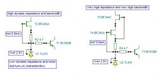
I'm with Ogir (hey, could you please write INPUT and OUTPUT on your little schematics?? ) on this. Cascoding the mosfet is probably not the way to go; but for driving the gates, you could use an EF driven by the driver, as Klaus has said, much better than a cascode which costs more headroom and offers no impedance advantage.
As for distortion, I've come to the conclusion that the high levels of H2 and H3 are not important, because the tube will be doing perhaps 2% compared to the output stage 0.05%. The only distortion you should try to reduce, bearing in mind that the H5 and higher will be somewhat masked by the higher levels of H2/H3 coming off the tube plate, is the higher levels, particularly odd. These are very low anyway, as you've correctly discovered.
I regard 0.05% H2/H3 as a physician would regard an indolent prostate tumour. It's not moving, it's not the musical problem, leave it well alone. The treatment is worse than the disease, particularly if lag compensation is required for stability.....
Cheers,
Hugh
Your training is forcing you to simulate and design for low distortion. This is certainly logical; but as something of a maverick, I approach the problem with blind faith and build it until it works well.
Last night I cranked up my two monoblocks and enjoyed another listening session. These amps use a 6SL7 front end, plate loaded (NOT a mu follower, which I've tried and didn't much like, not very musical), no cascode either on the driver or the mosfet output, and the simplest possible circuitry.
It sounded wonderful, brought tears to the eyes. Annie Lennox singing Primitive on 'Diva' was in the room, almost standing three feet before me. The realism on my new VSonics speakers (two way, 8" Peerless 884, silk dome Peerless tweeter, transmission lines) was amazing, and I realised why this amp was, and remains, my reference.
I'm with Ogir (hey, could you please write INPUT and OUTPUT on your little schematics??
) on this. Cascoding the mosfet is probably not the way to go; but for driving the gates, you could use an EF driven by the driver, as Klaus has said, much better than a cascode which costs more headroom and offers no impedance advantage.As for distortion, I've come to the conclusion that the high levels of H2 and H3 are not important, because the tube will be doing perhaps 2% compared to the output stage 0.05%. The only distortion you should try to reduce, bearing in mind that the H5 and higher will be somewhat masked by the higher levels of H2/H3 coming off the tube plate, is the higher levels, particularly odd. These are very low anyway, as you've correctly discovered.
I regard 0.05% H2/H3 as a physician would regard an indolent prostate tumour. It's not moving, it's not the musical problem, leave it well alone. The treatment is worse than the disease, particularly if lag compensation is required for stability.....
Cheers,
Hugh
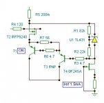
In the version i posted the driver is too hot and it starts oscillating at about 3nF, but the open-loop gain can be tweaked. Assuming that cascoding gives no early effect, the amp is a transconductance amplifier coupled to an integrator, quite similar to an instrumentation amplifier.
Since the cascoding of the driver makes the driver independent from the output, the transconductance can be tweaked by simply changing the output stage. I belive the proper value should be the highest possible that is stable on the particular real load you run it.
the "small-signal rate of error voltage correction" (i have never assisted to an electronics class, sorry) is Gin*Go*Rl/(Cgd+Cgs) = 0.04*Iin*Go*Rl/(Cgs+Cgd) = 6400 (V/V)/us at 10 mA , where Iin is the driver idle current in mA's. Wow, this looks like the inverse of a time constant! So the time constant can be tweaked by changing the bias current without having to add any new parts.
If the driver is not cascoded it becomes 0.04*Iin*Go*Rl/(Cgs+GoRlCgd) (roughly) 0.04*Iin/Cgd
AKSA said:Ion,
Your training is forcing you to simulate and design for low distortion. This is certainly logical; but as something of a maverick, I approach the problem with blind faith and build it until it works well.
Last night I cranked up my two monoblocks and enjoyed another listening session. These amps use a 6SL7 front end, plate loaded (NOT a mu follower, which I've tried and didn't much like, not very musical), no cascode either on the driver or the mosfet output, and the simplest possible circuitry.
It sounded wonderful, brought tears to the eyes. Annie Lennox singing Primitive on 'Diva' was in the room, almost standing three feet before me. The realism on my new VSonics speakers (two way, 8" Peerless 884, silk dome Peerless tweeter, transmission lines) was amazing, and I realised why this amp was, and remains, my reference.
I'm with Ogir (hey, could you please write INPUT and OUTPUT on your little schematics??
As for distortion, I've come to the conclusion that the high levels of H2 and H3 are not important, because the tube will be doing perhaps 2% compared to the output stage 0.05%. The only distortion you should try to reduce, bearing in mind that the H5 and higher will be somewhat masked by the higher levels of H2/H3 coming off the tube plate, is the higher levels, particularly odd. These are very low anyway, as you've correctly discovered.
I regard 0.05% H2/H3 as a physician would regard an indolent prostate tumour. It's not moving, it's not the musical problem, leave it well alone. The treatment is worse than the disease, particularly if lag compensation is required for stability.....
Cheers,
Hugh
I think my last simulations will make me follow your suggestions. I have just discovered that i had to add the exact ammount of compensating capacitance to make it stable in a certain capacitive load that i did remove with cascoding, so shows the maths are ok and the cascode is worthless.
You belive that cascoding the driver is worth the problems?
Your comments are of great help! Thanks.
Sorry for the desincronization with the replies.
Klaus,
MOSFETs are genuine transconductance devices, where the the input voltage and the output current are directly related, buffering would make the conversion less accurate (meaning decreased linearity). So the driver has to provide the necessary current, cascoding helps in this regard too. Cascoding has many benefits not just stability.
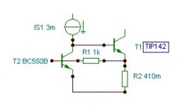
The driver current is a generally neglected issue, I cannot make estimations just instinctively feel that it`s about a considerable amount to handle such large input capacitances (fast enough), maybe at least 50mA.This needs a very healthy driver bias current or even better yet, buffer the gate drive with a follower.
MOSFETs are genuine transconductance devices, where the the input voltage and the output current are directly related, buffering would make the conversion less accurate (meaning decreased linearity). So the driver has to provide the necessary current, cascoding helps in this regard too. Cascoding has many benefits not just stability.
Ogir,
How much slew rate do you want at the mosfet output?
50mA is far more than is needed......
The change in voltage at the gate wrt rail is not great; only about a volt, the C/E of the driver is working as a concertina, like a phase splitter.
Anywhere from 5-10mA is fine; we are designing for human hearing.
You could supplement the gate drive with an EF driven from the driver collector and supported from its own CCS at the rail. That would work fine, greatly reducing current at the driver.
Cheers,
Hugh
Hugh,
It works but looks like a switching stage.You could supplement the gate drive with an EF driven from the driver collector and supported from its own CCS at the rail. That would work fine,
Lumba Ogir said:Klaus,
The driver current is a generally neglected issue, I cannot make estimations just instinctively feel that it`s about a considerable amount to handle such large input capacitances (fast enough), maybe at least 50mA.
Beware that the driver current in that circuit sets the open loop gain and the time constant of the integrator. High currents make the amp unstable and distortion is closely releated to current because it sets the amount of feedback.
Non-cascoded designs don't have this issue because transconductance goes with the bias current and output resistance goes as its inverse, so the effects cancel and the "mu" of the transistor becomes constant with current, if this effect dominates then it does only set the slew rate. Anyways the non-cascoded design has both effects and it needs more detailed analisys.
- Status
- This old topic is closed. If you want to reopen this topic, contact a moderator using the "Report Post" button.
- Home
- Amplifiers
- Solid State
- ccs-loaded sziklai