Originally posted by KSTR
Lineup,
Give the credits to Steve Eddy who proposed that center-tapped choke loading in the BT-thread the other day
Thanks for correct info.
Nevertheless, this circuit is, like Nelson somtimes puts it
so well
Steve Eddy is a good guy.
He knows more than some think - about good audio.
He likes to speak a bit, openly, & discuss.
But, in my opinion, there is less 'evilness' in Steve 'SE' Eddy, than inside several other.
And certainly more of sound & good knowledge, than in some others.
Eventhough, no person is or can ever be a pure Saint
Saint
not even me, lineup, as we all know
Lineup,
Give the credits to Steve Eddy who proposed that center-tapped choke loading in the BT-thread the other day
Thanks for correct info.
Nevertheless, this circuit is, like Nelson somtimes puts it
so well
AESTETHIC
this means a circuit is not necessarily absolute best hifi
what it means
is more
it is a circuit of beauty & symmetry in idea
Often we human percept symmetry as being 'beautiful', in our eyes/minds.
Top models' beautiful faces are most often very symmetrical.
Our conception of BEAUTY.
This has been explained as:
Good symmetry signals Good Health.
While asymmetry in nature can signal bad DNA or un-healthy individuals.
Steve Eddy is a good guy.
He knows more than some think - about good audio.
He likes to speak a bit, openly, & discuss.
But, in my opinion, there is less 'evilness' in Steve 'SE' Eddy, than inside several other.
And certainly more of sound & good knowledge, than in some others.
Eventhough, no person is or can ever be a pure
Saint not even me, lineup, as we all know
Now here the basic circuit idea (several key points still missing, of course). I continue to be quite thrilled from the performance/effort ratio it promises. Compared to my last foray into D2S realms (also in a circlotron config) this circuit is much simpler and behaves much better in several aspects (not in all, there are alway trade-offs). The circlotron is an old concept that deserves more attention, IMHO. It's not popular probably because the more complex supply. But circlotron + CPF with (a bjt master tranistor) seem to team up perfectly in the class-A domain... it's about time that I build this one i think, to get my feet on the ground.
- Klaus
- Klaus
Attachments
Lumba,
I think I see your point, but degeneration of the complete CFP would increase the Zout to just the value of the degeneration resistor in the circlotron config -- distortion values don't profit that much, so that trade-off seems questionable from that POV (there might be others, though -- but ie bias stability isn't as there is common mode degenerative feedback). Although I could happily live with some Zout when it is no more than 0.1 Ohms or so....
Or are you referring to the compensation scheme? This is indeed is not fully outgrown (neither is the whole circuit, it's a only study so far). It always is an issue of correct match of gate stoppers+MOSFET-C's, miller cap and drive impedance at the base... OTOH I'm pretty confident with the LR-shunt for EF-stages in general which lowers base resistance for AF while maintaining stability.
- Klaus
AKSA said:Ogir,
What ARE you trying to do in that little circuit?
I can't figure it out, and it's irritating me......
Hugh
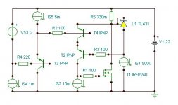
It seems relatively close to the one i've just built. T2 cascodes the driver at the voltage of the zener referred to the output. The zener is biased with a ccs and the output is buffered by an emmiter follower. The rare point is that the amplifier has no output, instead it is shorted to the supply, but this must be a mistake.
I've found that cascoding the driver cuts the [simulated] distortion by half and sends it to 8 ppm (0.0008%) at 20KHz on a 8R resistive load at full output (12Wrms).
Mine does not use the emmiter follower and cascoding is done by a couple of resistors (1K to the output and 10K to V+) plus a 100n cap in parallel with the 1K one. Mine is single-ended on a 2A sink.
Now i'm getting problems with ringing. It is extraordinary sensitive to the power supply voltage (for example a high positive voltage induces ringing at the bottom, while a low positive voltage induces ringing at the top). Do you have any idea about what is causing this effect and how could it be fixed?
Do you have any preference for ccs (both power ccs and small-signal ones) I'm using the one with two transistors and two resistors that uses Vbe of the programming transistor as a reference. Of course complexity-no-object, only performance.
BTW the cascoded amplifier sounds terrific as long as it does not get close to the ringing voltage (+/- 8-10V with +/-20V supplies). It seems to show all the detail in a way it becomes consistent with the music. It is also both neutral and warm as if it let untouched the original warmth of the music. Really really really good. No tubes so far.
EDIT: In simulations cascoding the driver removes mostly second harmonic (6 ppm instead of 15), but keeps the rest untouched so the subjective effects won't probably be spectacular.
My guess is that the problem comes from the heavy increasing Cdg/Ccb with lower Vds/Vce, shifting pole frequencies around. And with the CFP and CCS being of different type you have two such concurring and different effects which might counteract in a probably uncontrolled manner.ionomolo said:Now i'm getting problems with ringing. It is extraordinary sensitive to the power supply voltage (for example a high positive voltage induces ringing at the bottom, while a low positive voltage induces ringing at the top). Do you have any idea about what is causing this effect and how could it be fixed?
What models are you using, btw? I found that only andy_c's models of the IRFP244 etc are modeling the Cdg capacitance right (exact replica of the datasheet curves) and it's effects are clearly seen in simulation, eg with step responses and freq responses with varying Vds. For the basic circuit I quickly see massive overshoots and 20dB++ high Q freq response peaks, especially of course with slightly capacitive load... this usually gives oscillation.
Did you try any comensation schemes, like a miller cap (as in my circuit)? Do you drive it straight from the opamp output or is there significant source impedance?
At any rate it's nice to hear that you basically have a working amplifier and that it sounds great... this is encouraging...
- Klaus
i drive it straight away from the opamp and the models i'm using are the ones that come with orcad pspice. Surprisingly they replicate the shape of the envelope of ringing and its dependence with the source voltage really close to what i see on the scope. It seems that the models are fine (no idea if they match what's on the datasheet but they match what i see on the lab!)
Abot the miller cap, somebody said that the mosfet sziklai was a "pick your poison thing" ie, you need to compensate it until the mosfet becomes as slow as a power bjt. What i thought is that it was only about picking the exact ammount of poison to make the thing work without killing its advantages.
The cascode option is very special as the transconductance does depend on the bias current and so does the amount of feedback. (The circuit is a differencial transconductance amplifier + integrator (cgs-cgd)). In simulations the ccs works as a "distortion knob", very interesting.
Now i'm experimenting with cascoding as it reduces some variations that could cause unstability. The first result is 0.7 ppm THD at 25KHz and 10Vpeak (6W @ 8Ohms). Cascoding also affects more the second harmonic than the third, but playing with the voltages [this does not take power dissipation into account and may not be realistic] i have found that there is a certain ability to transfer energy from the second to the third and vice-versa. I will buy a full-cascoded prototype once i order some power PNP's from digi-key (2 weeks).
Anyways this looks very promising.
It's not the mosfet current
i have just realized that in a cascoded circuit the mosfet might be made to pass a big current without huge dissipation (actually doing this might need an extra supply or some serious dissipation, but now i'm trying to understand the problem before looking for the solution.
I have just made the mosfet to pass no less than 6A and it still shows the same ringing. Now i look with extreme suspicacy at the biasing of the driver cascode. I will post more when i get the results.
AKSA said:Manipulate the value of the gate stopper, and try increasing the bias current on the cascode. Try using up to 560R.
I hope this is helpful,
Hugh
Wow, i didn't see that... I will try this afternoon. May seem silly but sometimes i've got better stability by reducing the gate stopper.
What surprises me is that the problem persists even when the mosfet does not sense neither output current nor output voltage. Very strange. I have replaced many parts with ideal voltage and current sources and the problem seems to keep there or even increase. Degenerating sources with a resistor helps but it's attacking the symptoms instead of the problem and this gives increased distortion.
I love this project because it makes me think a lot!
Klaus,
sorry again for the error, I am substantially suspicious about unlinear coils and diodes, fortunately, in my view they are not needed there.
Are you actually working on a fully balanced amp?
sorry again for the error, I am substantially suspicious about unlinear coils and diodes, fortunately, in my view they are not needed there.
Are you actually working on a fully balanced amp?
Exactly, the most harmful capacitance in any location. In comparison, the nominal value of Cgd for the lateral Hitachi devices is just 10pF, impressively small, isn`t it. In fact, that is one of the main reasons for why they produce superior sound. I strongly suspect that it causes all the troubles here as well.My guess is that the problem comes from the heavy increasing Cdg/Ccb with lower Vds/Vce
Lumba Ogir said:Klaus,
sorry again for the error, I am substantially suspicious about unlinear coils and diodes, fortunately, in my view they are not needed there.
Are you actually working on a fully balanced amp?
Exactly, the most harmful capacitance in any location. In comparison, the nominal value of Cgd for the lateral Hitachi devices is just 10pF, impressively small, isn`t it. In fact, that is one of the main reasons for why they produce superior sound. I strongly suspect that it causes all the troubles here as well.
Not completely sure about the causes but i've just found a solution, adding a 4R7 resistor at the base of the cascoding transistor.
I've found that then second-harmonic distortion is a function of the ccs resistor (i havn't already tried changing transistors). The third harmonic does not depend so much on that value and becomes the dominant distortion. THD can be made 0.5 ppm at 25KHz 10Vpk output and 2.5 ppm at 16Vpk (16W @8Ohms). This gives a worst-case situation of 0.00025 % THD and with high efficiency loudspeakers (listening at 5-10W) it should be better than 0.00005% -but- Vbe changes with temperature will probably become 0.0005% or so.
Ion (a very elegant rocket motor, have you looked at the construction?),
My eyes are glazing over at some of the terms you are throwing around, but in general it does not surprise me that a stopper is needed on the cascode device. I know that slew rate is often focussed around the gate drive, but I'm really only looking for good linearity up to about 30KHz. Anything over this, and my amps go easily to 100KHz, is a bonus.
At this point we may have lost track of the circuit you are using; if PM does not work on this forum despite setting it on then you could use my email from my website.
However, could I raise a few issues? The distortion of my SE mosfet output stage is simmed at around 0.05%, mostly H2 with H3 about 10dB below, and this is significant for your circuit, as with a cascode you are changing the balance of distortion orders.
If you are to have distortion, and I admit it is inevitable and should be lived with, then you should try to highlight EVEN order, and downplay ODD order. This is because for most tonic scales only even order distortions confer harmony; odd order, beyond about five, starts to sound pretty objectionable.
Therefore, you may wish to consider NOT using a cascode on the output mosfets since you have found they reduce even at the expense of odd. At least try is without, and see how the sound compares, it will demonstrate qualities of distortion you never knew existed......
I have found that most distortion reducing mechanisms in amplifiers tend to reduce even at the expense of odd, at least within the limited topologies I've tried. This does have repercussions for musical pleasure.
Cheers,
Hugh
Hhm, there are no diodes here... and the those coils in the driver base can be realized as low current humbucking air coils, so no nonlinear stuff here...Lumba Ogir said:I am substantially suspicious about unlinear coils and diodes, fortunately, in my view they are not needed there.
If you count seriously making up my mind**) (including extensive simulations) about this CCS-Sziklai thing, then the answer is yes. A circlotron is per se balanced, anyway. As for actual building, I'll probably start with just the basic single ended CCS-loaded design as discussed here and then look forward, from the impressions and experience I get from it.Are you actually working on a fully balanced amp?
**) Among other topogical studies like succesful buffering of the MOSFET gates, I now actually found a simple way to extend the output power into regions where in plain class A one would normally suffer from cutoff in one ouput leg, going into class-B. This is not good at all, with a high feedback CFP (lots of xover spikes, etc). I dynamically modulate the bias so when needed it is increased that no output ever is starved of current, hence it remains in class-A always, even with 2R loads at full power. 100W into 2R and THD20<5ppm (
) looks promising for further work later on once I get the basics settled...- Klaus
Now when I think about that this first hand real-world experience seems logical, as the cascode device is an EF with capacitive load... prone to oscillation. Influence is perfectly reflected in simulation.AKSA said:My eyes are glazing over at some of the terms you are throwing around, but in general it does not surprise me that a stopper is needed on the cascode device.
Thanks again, Hugh and Ionomolo for sharing your findings.
And Ion, your quote "I love this project because it makes me think a lot!" describes it pretty well, this is exactly how I feel also. Seldom I had something that kept my brain cells so exited...
- Klaus
AKSA said:Ion (a very elegant rocket motor, have you looked at the construction?),
My eyes are glazing over at some of the terms you are throwing around, but in general it does not surprise me that a stopper is needed on the cascode device. I know that slew rate is often focussed around the gate drive, but I'm really only looking for good linearity up to about 30KHz. Anything over this, and my amps go easily to 100KHz, is a bonus.
At this point we may have lost track of the circuit you are using; if PM does not work on this forum despite setting it on then you could use my email from my website.
However, could I raise a few issues? The distortion of my SE mosfet output stage is simmed at around 0.05%, mostly H2 with H3 about 10dB below, and this is significant for your circuit, as with a cascode you are changing the balance of distortion orders.
If you are to have distortion, and I admit it is inevitable and should be lived with, then you should try to highlight EVEN order, and downplay ODD order. This is because for most tonic scales only even order distortions confer harmony; odd order, beyond about five, starts to sound pretty objectionable.
Therefore, you may wish to consider NOT using a cascode on the output mosfets since you have found they reduce even at the expense of odd. At least try is without, and see how the sound compares, it will demonstrate qualities of distortion you never knew existed......
I have found that most distortion reducing mechanisms in amplifiers tend to reduce even at the expense of odd, at least within the limited topologies I've tried. This does have repercussions for musical pleasure.
Cheers,
Hugh
I have already tryed the non-cascoded amp and it's my current reference, but i still want to break my head a little bit more on it.
Spice confirms what you are saying about cancelling even harmonics, but the final level of everything is so low that it's worth a try.
I tryed to pm you sometime ago you because i was doing a class A chipamp and thought about using an output stage with values very close to the ones you suggested and didn't want to post anything you had developed previously. Anyways this schematic is provisional and is pretty different from the initial one, so i hope there won't be any problems if i post it here.
My quest for megalow distortion is not aimed at avoiding distortion itself but rather at avoiding intermodulation, that's why i try to keep the amp at very low distortion upper the audio band, because intermodulation products of frequencies above 20KHz that all sources give and all filters pass because they have a finite slope would fall in the middle of the audio band.
I have to say that i thank a lot all the help and advise i'm receiving from you and all the forum members.
PD: Sorry for posting the most untidy schematic ever.
PD2: The voltages may need some adjustment to prevent this from being a 160W heater.
PD3: I'm still looking for a good voltage source for the cascode, so all the suggestions for it will be very useful.
EDIT: The transistors are what i have on hand and what i have on spice.
Attachments
Klaus,
I am asking because I`m very interested in your findings. You did once kindly recomend me the circlotron topology if you remember.If you count seriously making up my mind**) (including extensive simulations) about this CCS-Sziklai thing, then the answer is yes. A circlotron is per se balanced, anyway.
I wouldn`t miss it for the world.**) Among other topogical studies like succesful buffering of the MOSFET gates, I now actually found a simple way to extend the output power into regions where in plain class A one would normally suffer from cutoff in one ouput leg, going into class-B. This is not good at all, with a high feedback CFP (lots of xover spikes, etc). I dynamically modulate the bias so when needed it is increased that no output ever is starved of current, hence it remains in class-A always, even with 2R loads at full power. 100W into 2R and THD20<5ppm ( ) looks promising for further work later on once I get the basics settled...
- Status
- This old topic is closed. If you want to reopen this topic, contact a moderator using the "Report Post" button.
- Home
- Amplifiers
- Solid State
- ccs-loaded sziklai