burnedfingers said:Are the boards going to have provisions for stand offs for mounting?
Oops! Correct picture attached!
")
SY said:Since there's been a lot of interest lately in constant-current sources/sinks for use in tube amps and preamps, a few of us have been working behind the scenes to design a set of boards suitable for a wide variety of uses.
Hi,
I am wondering what are the current and voltage limits of this circuit (especially HV CCS) because you haven't provided for a small heatsink on the reg. transistor (also, the small trimmer will carry entire CCS current).
I have built a similar CCS for an LTP at 30mA and -B of 35V; heatsinking the regulating transistor was a must.
Regards,
Milan
JojoD818 said:navin,
you should get these boards for your upcoming amp in case you'll use ccs.
If only I haven't finished my ccs boards.
cheers
I was not sure if they'd ship to india.
Milan, there is indeed space allocated in the HV versions for a heatsink. These probably won't be suitable for a 100mA CCS at high voltage, but for more normal applications (say 1-20mA), there's plenty of room to attach heat sinking to the TO202/220 transistor.
I hate running DC through wipers, too, but there's no way around that without either sacrificing adjustability or increasing complexity. Running current through the track is no problem.
I hate running DC through wipers, too, but there's no way around that without either sacrificing adjustability or increasing complexity. Running current through the track is no problem.
I hate running DC through wipers, too, but there's no way around that without either sacrificing adjustability or increasing complexity. Running current through the track is no problem.
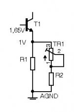
The real question is how much adjustability is really needed. The picture below shows a design I myself tend to use quite often. For example, for 10mA current, R1 is 120ohm, R2 is 120 ohm and Tr1 is 1k. Current can be set between 9 and 16mA and the wiper's current for 10mA is below 2mA.
Regards,
Milan
Attachments
That's a perfectly valid approach, albeit with more parts and slightly more difficult calculations (not an issue for you, but can be very much so for beginners).
These are not meant to be the ne plus ultra among CCS circuits, just good functional blocks which will ease the construction of amps and preamps. I think they do a good job of running up to the point of diminishing returns.
These are not meant to be the ne plus ultra among CCS circuits, just good functional blocks which will ease the construction of amps and preamps. I think they do a good job of running up to the point of diminishing returns.
navin said:I was not sure if they'd ship to india.
We are still working out logistics, but we certainly hope to be able to ship just about anywhere. This was one of the reasons for the compact board layout, a couple of PCBs should fit in an ordinary mailing envelope. Of course, if you wanted fifty...
moamps said:The real question is how much adjustability is really needed.
Fair point, but the circuit is designed to be as simple and flexible as possible. If you know exactly what you need, you can select R2 appropriately, and just add a link over where the trimmer is situated, the same approach will possibly work for higher current designs. The small resistors are at a 15mm spacing, so that does give a little leeway for larger units to be fitted.
Heatsinking was an issue discusssed at length!
pinkmouse said:Fair point, but the circuit is designed to be as simple and flexible as possible.
Simplicity and flexibility are worthwhile objectives but robustness and durability should be equally valid issues don't you think?
Anyways, I think you should provide a user manual to go with the board, highlighting the dos and the don'ts with respect to the application of your design.
Regards,
Milan
Dave, (Planet10), is sweating over his WP as we speak!
Seriously, this thread is purely for gauging interest, and getting the ball rolling. The final product will have full documentation, hopefully with a few applications as well, and all details of ordering, cost and suchlike will be posted in the GB forum. We might even see if we can get a spreadsheet going as well!
Seriously, this thread is purely for gauging interest, and getting the ball rolling. The final product will have full documentation, hopefully with a few applications as well, and all details of ordering, cost and suchlike will be posted in the GB forum. We might even see if we can get a spreadsheet going as well!
Mr Mouse,
Are the boards still going to be 6 to a sheet? Upon looking at your board it would appear there are holes for standoffs? A possibility that as I age I get less capable of seeing what is in front of me.
If you have a count going I will take 3 sheets of six boards.
On question... I am BC transistor poor. Is there something else I could use for a 10-16 mA load? I plan on using several of these for Cathode current source.
Attachments
No count as yet, all that messy business will happen later!
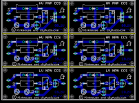
Yup, the boards are six to a sheet, two each of the three different types. There are 4 mounting holes on each sub-board, one in each corner. You won't need to use all of them, but they are there for flexiblity.
:edit: The transistors selected were the recommendation of Morgan Jones, I' m sure we will be able to come up with some equivalents by the time we get going.
- Status
- This old topic is closed. If you want to reopen this topic, contact a moderator using the "Report Post" button.
- Home
- Amplifiers
- Tubes / Valves
- CCS for tubes/valves: PCBs