Browsing vintage texts (as you do), there's an imperically derived general relation describing transfer characteristic for a triode :
Ia = P[Vg + Va/µ]n
(e.g Dow 1937 p122 equation 282p)
Ia anode current
Va anode potential
Vb grid potential
µ is amplification factor
P is a constant depending solely on geometry/construction
n is a constant depending on operating point and cathode parameters
For indirectly heated cathodes at normal operating points n is expected to be near 3/2, and the well known Child-Langmuir 3/2 power law is recognised. Whatever its exact value, the n term represents non-linearity in transfer characteristic for Ia versus Vg.
However, if Ia is constant, eg a CCS anode load, something very interesting happens it seems:
Define a new constant for convenience k =[Ia/P]1/n
Substitute k and rearrange Va = µ [k -Vg]
Diiferentiate to obtain transfer characteristic dVa/dVg = - µ
That is to say, the transfer characteristic is linear, there are no terms in n, no matter what the original value of n was !!!
Then a triode curve for Va versus Vg with a CCS anode load is simply a line of gradient µ, in principle. This is confirmed in Langford Smith, Radiotron Designers Handbook Ch 2 pp22 et seq, and by fig 2.15 p24.
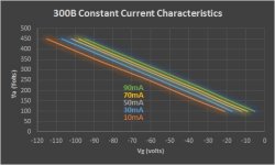
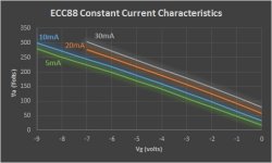
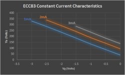
Transfer characteristics for real triodes valves in constant current mode can be found simply by transposing curves from published specsheets. I did this for three devices below 300B, ECC88, ECC83. They each confirm straight line transfer characteristics over a wide range of Ia and Va. Where there are wobbles I suspect the accuracy of my ability to read graphical values accurately, FWIW.
So as long as the relation between Ia, Va and Vg conforms to the general form above, the power term n such as 3/2 is eliminated from transfer characteristics for triodes operated with a CCS anode load, and a linear characteristic is available over wide operation conditions.
For this to be true, external load has to be very high impedance and CCS ideal BTW, so in real circuits an impedance buffer stage and good CCS seems essential if linearity is the aim.
Ia = P[Vg + Va/µ]n
(e.g Dow 1937 p122 equation 282p)
Ia anode current
Va anode potential
Vb grid potential
µ is amplification factor
P is a constant depending solely on geometry/construction
n is a constant depending on operating point and cathode parameters
For indirectly heated cathodes at normal operating points n is expected to be near 3/2, and the well known Child-Langmuir 3/2 power law is recognised. Whatever its exact value, the n term represents non-linearity in transfer characteristic for Ia versus Vg.
However, if Ia is constant, eg a CCS anode load, something very interesting happens it seems:
Define a new constant for convenience k =[Ia/P]1/n
Substitute k and rearrange Va = µ [k -Vg]
Diiferentiate to obtain transfer characteristic dVa/dVg = - µ
That is to say, the transfer characteristic is linear, there are no terms in n, no matter what the original value of n was !!!
Then a triode curve for Va versus Vg with a CCS anode load is simply a line of gradient µ, in principle. This is confirmed in Langford Smith, Radiotron Designers Handbook Ch 2 pp22 et seq, and by fig 2.15 p24.
Transfer characteristics for real triodes valves in constant current mode can be found simply by transposing curves from published specsheets. I did this for three devices below 300B, ECC88, ECC83. They each confirm straight line transfer characteristics over a wide range of Ia and Va. Where there are wobbles I suspect the accuracy of my ability to read graphical values accurately, FWIW.
So as long as the relation between Ia, Va and Vg conforms to the general form above, the power term n such as 3/2 is eliminated from transfer characteristics for triodes operated with a CCS anode load, and a linear characteristic is available over wide operation conditions.
For this to be true, external load has to be very high impedance and CCS ideal BTW, so in real circuits an impedance buffer stage and good CCS seems essential if linearity is the aim.
Attachments
Last edited:
Latest news: ECC83 found not guilty!
"Following detailed investigations the ECC83 was found not guilty of distorting music, and told that it could leave court without a stain on its character. Supporters outside the court said "We told you so". Speaking though its lawyer, the ECC83 said "I intend to pursue those who have been blackening my name by spreading rumours about my infidelity. Of course, if placed in a difficult situation such as low resistance load or poorly chosen bias point I may be tempted to stray - but that is entrapment! When free to act according to my own principles I remain true to the music."
"Following detailed investigations the ECC83 was found not guilty of distorting music, and told that it could leave court without a stain on its character. Supporters outside the court said "We told you so". Speaking though its lawyer, the ECC83 said "I intend to pursue those who have been blackening my name by spreading rumours about my infidelity. Of course, if placed in a difficult situation such as low resistance load or poorly chosen bias point I may be tempted to stray - but that is entrapment! When free to act according to my own principles I remain true to the music."
Well NFB isn't required to achieve linear transfer characteristic in principle here. And transistors aren't nearly this linear per se without NFB ............all manner of party tricks are possible with NFB of course, but this is a separate issue and not in play here.if you linearize the tube and use NFB you will have an equivalent transistor circuit
CCS, linearizing effect of...
Nice work, LuckyTheDog. Nice indeed. I was going to argue that the (Ia/P)(-1/n) equation isn't a constant. But then ... you "made it a constant" by saying, "using a CCS". Excellent.
In theory then, until the final stage, one could use VAS topologies that exclusively employ CCS anode loads, and necessarily large grid pull-down resistors in following stages (to keep that impedance high, and to keep the k as close to constant as possible.)
Got it.
GoatGuy
Yes, Mu, that's how it is defined at constant current. It supposed to be constant.
Only problem is that the grid1 on most tubes is close enough to the cathode surface to show grid wire proximity effects. Old tubes (well spaced for linearity) may show close to 3/2 power for the grid1, but later tubes are closer to square law. Usually it varies from somewhat above 2.0 power law at low currents down to less than 1.5 power law at high currents (may be exponential even at very low current). Grid2 on the other hand is far enough away to operate close to 3/2 power law reliably.
So the mis-tracking between the grid1 power law and the grid2 power law causes Mu to vary some as current increases (generally increases until saturation effects make it drop again). But the Mu will usually stay fairly constant if the current is kept constant.
That 12AX7 has such low grid1 gm (like an old tube, its got more space between g1 and cathode) that it is close to a 3/2 power law on g1, so Mu stays fairly constant versus current.
Last edited:
Let's see … then by the observation that "real world anode circuits" have an effective impedance less than infinite (real loading, both a/c and DC), and recognizing that the closer to infinite impedance the load gets, the more linear will be the triode's amplification, then the opposite also stands to reason: the worst linearity will be had when the anode voltage is held constant, as in a cascode arrangement. (Cascode loads offer "near zero impedance" to the tube, the opposite of the CCS load).
One could even imagine a actively "negative resistance" load (where increased anode current raises the anode voltage), which might be hard to engineer, since it could easily race to rail clamping or oscillation. But the limit of stability would also be easily calculated for a given tube of a certain mu and quiescent operating state.
Fun stuff.
GoatGuy
"One could even imagine a actively "negative resistance" load "
Bootstrap the load R with more AC signal than the plate is putting out.
----------------------
There are a few tricks around. One can put a damper diode or such below the cathode to get grid1 operating closer to 3/2 power law, but that will lower the Mu and increase the Rp.
The Aikido input stage effectively puts a 3/2 power law load R (the top tube) on the bottom tube, so it stays close to linear.
One can also put a linear degeneration resistor below the cathode to lower the grid1 power law.
When grid1 and plate have the same power law, no distortion.
The Western Electric (WE) harmonic neutralizer works this way for removing odd harmonic distortion for an LTP.
And putting a linear load R on the plate can be looked at as degenerating the plate to a lower power law (which increases distortion typically, since the grid1 is operating at a higher power law then).
Last edited:
Bootstrap the load R with more A/C than plate is generating. I agree.
Made me start to think though … what about symmetrically tainting (intentionally) the signal by having a fairly heavily loaded stage '1' with a voltage-divider (to get back to a gain of 0 dB), followed by a second exact duplicate stage; the first stage inverts the signal's A/C phase, the second stage exerts its power-law behavior on the signal's peaks which were once negative excursions. Seems that if '2nd harms are kind of sweet', then symmetrically anti-compressing the signal ought to even be sweeter.
Almost worth an experiment.
Almost
GoatGuy
I think that is how one gets odd harmonic distortion. 3rd H is not too bad sounding.
If each stage only compressed with 2nd harmonic distortion, then they would cancel dist.
Some designs intentionally use a distorting driver stage to cancel 2nd H with the output stage. But the odd harmonics add up typically.
Here's another trick. Connect a diode (VT) from (pentode) cutoff bias -V to grid1 of a pentode. ( diode plate goes to grid1, diode cathode to cutoff bias -V) Now if you put an AC --current-- signal into the grid1/diode combo, the diode does 2/3 power I to V conversion. The pentode then does 3/2 power (nominal) V to I conversion. Net result is linear I to I current gain (if the diode conductance is less than the pentode gm). This is the vacuum tube current mirror with gain.
Putting current drive into the screen grid of a pentode works similarly, at least until the plate V gets down to near the screen V, and the screen starts sucking more than just proportional plate current.
Last edited:
In theory then, until the final stage, one could use VAS topologies that exclusively employ CCS anode loads
Why only until the final stage? Surely we want the finals to also be low distortion?
By the way, tube expanders used to be widely found in consumer electronics. I've never really looked at one that close in the TV schems, I only look at the video parts. Might be interesting though.
MrCurwen, as far as I understand power-amplifier electronic theory, the last stage is really mostly about amplifying current and not voltage. Indeed, if you look at a typical OTL vacuum-tube or silicon-transistor amplifier output stage, all the voltage amplification has happened before the final. In the silicon world, the final is merely a voltage-follower, having the very useful characteristic of very high input impedance, and very low output impedance. No voltage gain.
If you look at a typically power vacuum-state amplifier, whether in push-pull, or single-ended topology (makes no difference), the output tubes "job" is to strongly modulate the current fed into the windings of the output transformer. The OT's job obviously is to "match the impedances" between the output load (2, 4, 8, 16 ohms) and the optimal design characteristics of the output tube(s).
Again - as far as I'm aware - this consideration is also why "ultra-linear taps" were added to OPTs, and the topology became popular for pentode-output stages. Can't do that with triodes. But you can multiply voltages with triodes, even in the final stage.
Could be full-of-beans, but the above all kind of makes sense with regard to the plethora of real-world designs I've reviewed over the last 4 decades.
GoatGuy
"the output tubes "job" is to strongly modulate the current fed into the windings of the output transformer. "
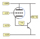
Put a constant Beta (current gain) power bipolar transistor under the triode's cathode (cathode connects to base terminal), and connect the collector to the tube plate. Now you have a 3 terminal device (grid input, emitter, collector/plate) that has triode Mu V gain, and bipolar Beta current gain, well, bipolar current output (current gain would be infinite from grid).
A tube Darlington, or "tubington".
Last edited:
Yes. There's no escaping non-linearity in the current domain, normally near 3/2 law. In cascode case linearity depends on how current is then converted to voltage in the top half of the cascode - if conversion is linear ie resistive then that is as non-linear as it gets in principle - if conversion follows exact inverse law then it gets perfectly corrected, so devil's in the detail I think.Let's see … then by the observation that "real world anode circuits" have an effective impedance less than infinite (real loading, both a/c and DC), and recognizing that the closer to infinite impedance the load gets, the more linear will be the triode's amplification, then the opposite also stands to reason: the worst linearity will be had when the anode voltage is held constant, as in a cascode arrangement. (Cascode loads offer "near zero impedance" to the tube, the opposite of the CCS load).
Optimal linearity for conventional triode operation is when anode load impedance is infinite, so mucking with negative impedance via feedback is never going to improve !
"In cascode case linearity depends on how current is then converted to voltage in the top half of the cascode - ...."
One could look at the cascode as a variant of the Aikido input stage setup, but with a very low Rp tube up top. In the Aikido, the gm and cathode rk need to be scaled proportionally between top and bottom. (normally an equal top and bottom setup in the Aikido) But the gain is only constant at constant current, so maybe need a CCS on top of both. Looks unstable.
Maybe put a tube diode in series between top and bottom tubes to inject more 3/2 power Z.
Or put a HV diode up top for the load. 3/2 power V to I followed by 2/3 power I to V.
----------------------------------------------------------------------
Yep, Tubington
Can also put a PNP on the top side instead. (plate to base, cathode to collector).
Last edited:
Not to my way of thinking.....
Doing the above will not make a transistor circuit perform the same way a tube circuit will. The tube circuit will have the warmth! If you do not believe me, try listening to the transistor circuit first. If that does not convince you, try touching the two devices in operation!
if you linearize the tube and use NFB you will have an equivalent transistor circuit
Doing the above will not make a transistor circuit perform the same way a tube circuit will. The tube circuit will have the warmth! If you do not believe me, try listening to the transistor circuit first. If that does not convince you, try touching the two devices in operation!
- Status
- This old topic is closed. If you want to reopen this topic, contact a moderator using the "Report Post" button.
- Home
- Amplifiers
- Tubes / Valves
- CCS anode load overcomes 3/2 law non-linearity