Here is some stuff you may find interesting. Beware also of making the emitter pull down resistor in an emitter follower too high in value. This is an invitation for oscillation especially if there is some capacitance load to ground on the transistor connected to the follower emitter - this was the problem min the kx2 Amp VAS stage were I set the follower emitter load resistor value to 10k. Changing it to 1k resolved the issue completely.
For cascodes, I always place a 470 to 1k resistor in the base of the cascode device as close to the transistor as possible as shown in Lee Knatta's post above. With cascodes its very easy to create an oscillator, so you really have to damp the base and as Nelson has suggested, the emitter as well.
https://hifisonix.com/cascode-amplifier-oscillation/
Prior to posting here I experimented a bit with lowering the cascodes base stopper resistors to 100R each to see if it gets worse (easier to solder a resistor in parallel than to exchange the component for another higher value one). It got worse and this is why I'm suspecting that the cascodes might be involved in oscillation.
With 1k, I'm at the higher end of the recommended spectrum already.
What is your recommendation regarding the maximum base stopper resistor?
What could be the potential consequence of overdoing it?
With 1k, I'm at the higher end of the recommended spectrum already.
What is your recommendation regarding the maximum base stopper resistor?
What could be the potential consequence of overdoing it?
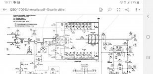
Once you can use an op amp for all the low level processing, why would you bother with cascodes? Well...you can cascode an entire op amp or use folded cascodes for better headroom, but then...QSC cause most good opamps have a cascode of some sort as the input stage .
And... not all cascodes are born equal.
And... not all cascodes are born equal.
Attachments
One result of overdoing the stopper might be noise, another with a very high value would be modulation of the cascade emitter voltage due to the base current causing a voltage drop across the stopper resistor.
I’ve used 470 ohms and 1k to good effect. You must put the stopper resistor right next to the cascode transistor base and keep the total amplifier<> cascode transistor loop as tight as possible to minimise trace inductances. The 100 ohm damper between the amplifier transistor and the cascode emitter is also a good addition per NP’s comment above.
I’ve used 470 ohms and 1k to good effect. You must put the stopper resistor right next to the cascode transistor base and keep the total amplifier<> cascode transistor loop as tight as possible to minimise trace inductances. The 100 ohm damper between the amplifier transistor and the cascode emitter is also a good addition per NP’s comment above.

Brief update: The DC offset and oscillation I was observing had nothing to do with the cascode arrangements shown in my schematics earlier. I just like to point this out.
The issues were related to a different cascode however and the root cause was trivial: The cascode of the VAS was chosen with too low voltage across the VAS transistors. Just a stupid mistake. Lesson learned: Make sure the cascoded transistor has enough Vce headroom to work well.
I still get some offset and oscillation however once I connect my DAC to the amplifier input and need to figure out what is wrong. The oscilloscopes square wave generator as input does not cause this issue. In case this is related to any cascodes, I might post here. Else, I will just sort out another stupid mistake I made.
spot on, missed this one.If I am reading your circuit correctly your cascode (Q7) is referenced to 0 V Via R17. It should referenced to 3-4 volts above the -ve rail after R26. You can use a Zener or two LED’s to create the correct voltage.
Thank you Sir.
- Home
- Amplifiers
- Solid State
- Cascodes- the truth is out there...