@ Suzie: I apologize for my posting style. It was not my day.
Many thanks for that udok.
Never seen any BD139 or 140 of recent make to be grouped, hence probably the absence of groups in the sheets.
-16 grouping: BD139-16 STMicroelectronics | Mouser Australia
-10 grouping: BD139-10 STMicroelectronics | Mouser Australia
-16 grouping: BD139-16 STMicroelectronics | Mouser Australia
-10 grouping: BD139-10 STMicroelectronics | Mouser Australia
Does anyone know, whether the STM devices have hf behaviour comparable to the Onsemi / Fairchild ones? I think, the models we are using mostly are valid for the Onsemi versions.
There is, e.g., some rumor that the older Phillips version had different (much better) hf behaviour.
Matthias
Sadly nearly every spice model is bad.
The only important thing seems to be to have any model for the webpage.
The old Philips and Infineon models are good.
But there are exception too, e.g. the BCP56 has an early voltage of 8 volt (!).
I would like to have Mextram models of some important devices.
Does anyone know where to get them?
Regarding HF, you could compare parameters TF and CJC (Transit Freqency and Cbc capacitance)
Last edited:
Hi udok,
The problem now is that Onsemi at least still have capacity diagramms in the datasheet, but STM do specify literally nothing related to dynamical behaviour.
SOAR specifications are apparently identical; this indicates that the devices are in fact comparable. But I would like to know for sure ...
Kind regards,
Matthias
people agree that Bob Cordell's models (available from his web page) are quite reliable. I cannot check that but reading his book I would say he has done really careful work.Sadly nearly every spice model is bad.
The only important thing seems to be to have any model for the webpage.
The old Philips and Infineon models are good.
But there are exception too, e.g. the BCP56 has an early voltage of 8 volt (!).
I would like to have Mextram models of some important devices.
Does anyone know where to get them?
Regarding HF, you could compare parameters TF and CJC (Transit Freqency and Cbc capacitance)
The problem now is that Onsemi at least still have capacity diagramms in the datasheet, but STM do specify literally nothing related to dynamical behaviour.
SOAR specifications are apparently identical; this indicates that the devices are in fact comparable. But I would like to know for sure ...
Kind regards,
Matthias
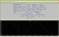
To help with the design of Suzie's 3-stage amp, i added a third
amplifier to the MulitLoop LTSpice example.
The example consist of up to 3 amplifiers in a loop.
The first one has Gain of 10e3 and a unity gain frequency of 30 MHz,
the second one has gain of 100 and a UGF of 100 kHz.
The third one is identical to the 2nd amp.
In addition i added a very simple output buffer stage to see if
the added loop gain helps in reducing distortion.
This buffer has serious problems with crossover
distortion but it is a quick test.
The LTSpice file and a picture with a simple stability test is
appended. The square wave test looks very good without
overshoots.
The simulation does three sweeps:
- only the first amplifier is in the loop
(the main one with 10e3 gain up to 30MHz, similar to a good Opamp)
- additionally amplifier 2 in the loop (Amp 2 has Gain 100 up to 100kHz)
- additionally amplifier 2 and 3 are in the loop (Amp 3 is like amp 2)
The log file (View->Log) records the THD values @ 1kHz:
It is nice to see that indeed more loop gain helps with THD:
- 86 dB with 1 amplifier in the loop
- 110 dB with 2 amplifiers in the loop
- 119 dB with 3 amplifiers in the loop
In principle this concept could be implemented with 3 opamp models,
or three discrete stages similar to Suzies amp.
Nevertheless a class-A amp could sound better at low volume as it
has zero crossover distortion")
amplifier to the MulitLoop LTSpice example.
The example consist of up to 3 amplifiers in a loop.
The first one has Gain of 10e3 and a unity gain frequency of 30 MHz,
the second one has gain of 100 and a UGF of 100 kHz.
The third one is identical to the 2nd amp.
In addition i added a very simple output buffer stage to see if
the added loop gain helps in reducing distortion.
This buffer has serious problems with crossover
distortion but it is a quick test.
The LTSpice file and a picture with a simple stability test is
appended. The square wave test looks very good without
overshoots.
The simulation does three sweeps:
- only the first amplifier is in the loop
(the main one with 10e3 gain up to 30MHz, similar to a good Opamp)
- additionally amplifier 2 in the loop (Amp 2 has Gain 100 up to 100kHz)
- additionally amplifier 2 and 3 are in the loop (Amp 3 is like amp 2)
The log file (View->Log) records the THD values @ 1kHz:
It is nice to see that indeed more loop gain helps with THD:
- 86 dB with 1 amplifier in the loop
- 110 dB with 2 amplifiers in the loop
- 119 dB with 3 amplifiers in the loop
In principle this concept could be implemented with 3 opamp models,
or three discrete stages similar to Suzies amp.
Nevertheless a class-A amp could sound better at low volume as it
has zero crossover distortion
Attachments
Hi udok,
My impression was that Pavel is aware of a rigorous mathematical method. It should allow to shape a higher-order loop gain (shift poles and zeros of transfer function, perhaps with some constraints) in such a way that the closed-loop circuit will not overshoot in an exact sense, without the aid of an additional input filter.
But thank you anyhow for the effort. Hope the others will also like your way of model-making, especially when combining with more concrete devices like in your later post. (Using an ideal voltage-controlled current source, G block, instead of the concrete diff input stage is an equally interesting excercise when looking for distortion sources.)
Kind regards,
Matthias
I agree that this is an intuitive approach. This is the way I have been thinking about similar problems related to my design, too.... I could not think of a better method than trial and error.
Maybe BesPav can help us?
My impression was that Pavel is aware of a rigorous mathematical method. It should allow to shape a higher-order loop gain (shift poles and zeros of transfer function, perhaps with some constraints) in such a way that the closed-loop circuit will not overshoot in an exact sense, without the aid of an additional input filter.
But thank you anyhow for the effort. Hope the others will also like your way of model-making, especially when combining with more concrete devices like in your later post. (Using an ideal voltage-controlled current source, G block, instead of the concrete diff input stage is an equally interesting excercise when looking for distortion sources.)
Kind regards,
Matthias
Last edited:
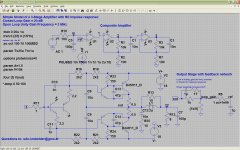
Ok, to make this Multi-Loop ampifier less abstact, i replaced
the ideal Spice parts with LM4562 opamps.
I promise this is the last post today regarding this thema!
If Suzie feels, that this does deviate too much from the original post,
the administrators could please shift this in a separate thread.
I improved the output buffer with a diamond like structure.
Voltge swing is about 15 Volt Peak with 18 Volt supply and 6 Ohm load.
And distortion really shines, especiall at lower frequency
(even Spice can not measure it anymore)
At 10 kHz with a 15 Volt Peak Sine in 6 Ohm THD is about 130 dB
(at least Spice is saying so).
One little drawback of the composite amp concept is that it does not
help much at higher frequencies, and 10k is already high,
as the 2nd and 3rd stage has a unity gain frequency of 160kHz.
I think the output buffer is pretty and simple and with the addition of
two transistors it is short cirucit proof.
I do not have the time to build this, but if someone has interest in
building this, i would like to help out with the theoretical part.
An idea is to add an output buffer with voltage gain.
With higher supply voltages and overcurrent protection
this could become one of the best amplifiers in the wild.
the ideal Spice parts with LM4562 opamps.
I promise this is the last post today regarding this thema!
If Suzie feels, that this does deviate too much from the original post,
the administrators could please shift this in a separate thread.
I improved the output buffer with a diamond like structure.
Voltge swing is about 15 Volt Peak with 18 Volt supply and 6 Ohm load.
And distortion really shines, especiall at lower frequency
(even Spice can not measure it anymore
)At 10 kHz with a 15 Volt Peak Sine in 6 Ohm THD is about 130 dB
(at least Spice is saying so).
One little drawback of the composite amp concept is that it does not
help much at higher frequencies, and 10k is already high,
as the 2nd and 3rd stage has a unity gain frequency of 160kHz.
I think the output buffer is pretty and simple and with the addition of
two transistors it is short cirucit proof.
I do not have the time to build this, but if someone has interest in
building this, i would like to help out with the theoretical part.
An idea is to add an output buffer with voltage gain.
With higher supply voltages and overcurrent protection
this could become one of the best amplifiers in the wild.
Attachments
Hi udok,
people agree that Bob Cordell's models (available from his web page) are quite reliable. I cannot check that but reading his book I would say he has done really careful work.
The problem now is that Onsemi at least still have capacity diagramms in the datasheet, but STM do specify literally nothing related to dynamical behaviour.
SOAR specifications are apparently identical; this indicates that the devices are in fact comparable. But I would like to know for sure ...
Kind regards,
Matthias
Yes, they are on the better side. But the problem is that you do not know
how the transistor from mfg X compares to them.
Why not measure the data yourself and fit the model parameters yourself? Bob Cordell's book outlines several good processes and algorithms for parameter extraction, and another excellent resource is Ron Kielkowski's book (link). I had the good fortune to buy it new, from a bookstore, years ago. Now that it's out of print, the price has risen.I would like to have Mextram models of some important devices. Does anyone know where to get them?
Once you've extracted and fit a couple of devices with the pre-Mextram modeling equations, you'll have the skills and "muscle memory" to fit Mextram. Give it a try! It's fun!
Maybe BesPav can help us?
Hi, udok!
Let’s try.
There are some severe math, so excuse me if i’ll go excessively deep in that forest.
Example you’ve shown assumes very different approach, while an order of UGF differencies used.
Please, allow me to start from poles and zeros.
Theare are three common usable compensation schemes:
1. First order or dominant pole compensation

Unconditionally stable, but for such a feedback depth are very high bandwidth is needed. Say, for ~100 dB at 20 kHz with -20 dB/dec slope and -20 dB amplitude margin we’re run for 20 GHz output stage.
Unpractical at all.
2. Second order slope (-40 dB/dec) with some part going at first order (-20 dB/dec) around unity-gain frequency.

Conditionally stable, but easy for design and ready for any moderate feedback depth with good OPS.
3. Third order slope with first order part around UGF.

Conditionally stable, hard to design, but allows for unprecedently deep feedback with a real well-known OPS’es.
What was done.
1. Open parentheses and differentiate parts for complex and real fractions.
2. Express poles and zeros freq’es by relations.
3. Try to minimize complex fractions.
4. If there are a mathematically solveable limit present then we have a relation between them.
5. First poles are commonly present inside an opamp’s as dominant (could be taken from OLG plots), just substitute those values for estimate needed zero’s frequencies.
I already showed an example for third case and it clearly corresponds with
My impression was that Pavel is aware of a rigorous mathematical method. It should allow to shape a higher-order loop gain (shift poles and zeros of transfer function, perhaps with some constraints) in such a way that the closed-loop circuit will not overshoot in an exact sense, without the aid of an additional input filter.

Check, that input filter at centered .TRAN simulation doesn’t connected and we see intrinsic two-opamp composite response.

Sorry, if i went into the wilds.
PS. Your example with a 10x differences between UGF’s is known approach, but we went a little more complicated way.
Last edited:
Thanks for the link Mark,
Another good link is the Agilent IC-CAP Modelling Handbook from Franz Sischka.
From there i have all my Spice knowledge. There is an older and version from 2001,
which is not as thick as the newer one.
You are totally right with your suggestion! Problem is that you need a lot of time and equipment to do it right.
Especially with power transistors a pulse measurement is required.
It is on my list of the 100 things to do
Hey
for those who think that <1ppm is only possible in simulation, please "get out more". The Audio Precision systems and similar can resolve down to about 2.5ppm and they re about to release or have released some new software to go lower than that. With spectrum analysis and fancy math one can mine out distortions in the <1ppm range.
There have always been real amplifiers that have THD so low that it cannot be measured accurately with the test equipment of the day.
Based on the "any distortion is bad distortion" approach, the goal should always be to get the lowest number possible. It is easy to do with small-signal circuits and only slightly harder for power amps. It helps if you know what the load will be and do not have to design it to be all-things-to-all-people, although even that is not impossible given the many very bright designers in the world - and on this forum. To me, Suzyj is in that class.
Even if it could be shown that the simulations are always an order of magnitude better than can be achieved with real parts - even two orders of magnitude - that would make it all the more compelling to shoot for the lowest number possible. Maybe you are willing to accept 50ppm like Bigun, but if one of these "sim <> real" ratios is true, then he would aim for 5ppm or 500ppb so that his physical amp would be 50ppm.
The circuits I've built are pretty simple and the sims run very fast yet I get good numbers. When you see the six-zero result the first time it is very exciting, but then you are spoiled forever... hehe... never quite satisfied... My test equipment at this point is obsolete, resolving 20ppm, so all I can verify is that I cannot measure what I build and then know it is <200ppm. Fortunately, I have occasional access to an AP equipped lab with friendly people.
Last edited:
Hi nauta,
To accurately measure distortion down that low, a lot of care must be taken with the setup and execution of the test. The lower you want to get to in THD numbers, the more serious your test will become. No longer do you just connect the cables and go!
What are you using for test equipment?
To accurately measure distortion down that low, a lot of care must be taken with the setup and execution of the test. The lower you want to get to in THD numbers, the more serious your test will become. No longer do you just connect the cables and go!
What are you using for test equipment?
Hi Nautica,
You don't necessarily need expensive AP gear to measure reasonably low distortion levels. My own setup consists of an LT AN67 based source, dummy load, passive T notch filter and venerable HP3585B spectrum analyser. I've used that to measure 1ppm distortion (at 1KHz).
Getting an accurate distortion measurement is a good way to waste rather a lot of time.
I think the point is that while an amp that simulates to 1ppm probably won't get that far in reality, an amp that simulates 100ppm most definitely won't, so you need to set your simulation bar higher than your measurement bar. In reality I'll be pretty pleased if I can hit say 5ppm at 10KHz on a real circuit, as that'll then be better than anything I've built so far.
Happened to be reading this .pdf and the Harris 2539 (page 23) reminds me of your design
a bit, note that the dual diff pair is driven directly:
https://web.stanford.edu/class/archive/ee/ee214/ee214.1042/Handouts/ho15opamp.pdf
a bit, note that the dual diff pair is driven directly:
https://web.stanford.edu/class/archive/ee/ee214/ee214.1042/Handouts/ho15opamp.pdf
- Home
- Amplifiers
- Solid State
- Cascading diamond buffers - a cheap low THD 10W amp with TIP41C