In the Right one :There are 4 output pins per each 14 pin op-amp. You need to post the pin number and the voltage.
PINS Voltage
1. 0
2. 0
3. 0
4. +16
5. 0
6. 0
7. 0
8. -13.94
9. -3.40
10. 0
11. -15.75
12. 0
13. -3.37
14. -13.95
MIDDLE ONE:
Pins Voltage
1. -14
2. -6.80
3. -13.88
4. -13.88
5. -13.35
6. -10.94
7. -14
8. -13.32
9. -13.32
10. 0
11. -15.75
12. 0
13. -13.33
14. -13.32
LEFT SMALL ONE:
Pins Voltage
1. -13.12
2. -2.48
3. -11.84
4. -15.78
5. -13.88
6. -13.15
7. -11.95
8. 0
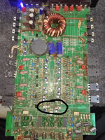
yes,it is an old photo.Is that an old photo? I see the fixative on some components.
May be i am checking the voltage with one terminal grounded and second terminal on pins with multimeter.You don't have positive supply voltage on two of the ICs. Why?
Tell me if i am wrong.
30V In the right side and 0.25V in the Middle one and 0.25V in the left side's small op-amp.With a meter, black on pin 11, red on pin 4, what is the DC voltage?
If you got that wrong, all the rest are unreliable. Place the black meter probe on one of the non-bridging speaker terminals and repost the voltages. Do it on the 14 pin op-amp on the right of the photo first. Copy and paste:
Pin 1:
Pin 2:
Pin 3:
Pin 4:
Pin 5:
Pin 6:
Pin 7:
Pin 8:
Pin 9:
Pin 10:
Pin 11:
Pin 12:
Pin 13:
Pin 14:
Pin 1:
Pin 2:
Pin 3:
Pin 4:
Pin 5:
Pin 6:
Pin 7:
Pin 8:
Pin 9:
Pin 10:
Pin 11:
Pin 12:
Pin 13:
Pin 14:
Please can you clarify what do you mean by non-bridging speaker terminals by using or marking in this photo.the non-bridging speaker terminals
Attachments
- Home
- General Interest
- Car Audio
- Car Amplifier have power but no sound. Please help me