The biggest HF impedance of a small capacitor is the inductance due to the spread/length of the lead outs.
If you must have a 0.2" pin pitch then a cap that is roughly that width will not have excessive inductance.
However, if you can accommodate a 0.1" pin pitch, then a physically smaller cap will inherently have a lower inductive impedance.
There are many 0u1F 0.2" caps that look like smaller caps with spread out leads. Post35 shows an example.
If you shorten these lead outs and close them up to 0.1" pin pitch (be very careful to not crack the epoxy coating) you end up with less inductance than the big 0.2" shown in link4 of post36.K104K15X7RF5TH5 Vishay / BC Components | Mouser
Pick a smaller X7R for decoupling, if you can use 0.1" pin pitch.
Many times the "close to the IC pins" and "narrow pin pitch" advice and practice for split-rail supplies is rendered useless because most people don't know that the really important path is rail-to-rail, right at the chip. Without a seperate rail-to-rail decoupler the split-rail decouplers must be arranged with the caps forming the shortest path between the chip's supply pins, and the center tap gets connected to GND (the inductance of that trace/wire is much less important, HF load decoupling -- returning load current from GND to the supplies -- is more or less irrelevant). Any output snubbers on the chip should go to that GND tap as well, they also need a low inductance path.
Most schematics don't even give the slightest hint to that (using those dreaded GND symbols), and as a consequence, many layout aren't perfect.
Most schematics don't even give the slightest hint to that (using those dreaded GND symbols), and as a consequence, many layout aren't perfect.
Last edited:
Kstr,
with a dual polarity supply and an output that passes current through the load to Power Ground, the decoupling must include the Power Ground.
It is not sufficient to connect Rail to Rail, as this applies when the Load current returns direct to one of the rails and that generally does not apply to a dual polarity amplifier.
Consider first the half wave current going from +ve rail through the amplifier to the output, then passing through the load to the Power Ground.
That current route does NOT include the -ve rail.
The current fed into the +ve pin MUST return to the Power Ground.
When the next half wave current is demanded by the load, the current passes from the -ve rail through the amplifier out to the load and returns from the load to the Power Ground. This time the +ve rail is NOT in that current route.
In each case the half wave draws and returns it's current around a loop from rail to Power ground.
The decoupling must allow that route to work at very high frequencies.
This requires that the decoupling cap in the +ve half connects the +ve Pin to Power Ground
and
The decoupling cap in the -ve half connects the -ve Pin to the Power Ground.
The Power Ground is the junction between the decoupling caps.
I was talking about high frequency (100kHz++) decoupling to provide/enhance stability, foremost. For audio return currents electrolytics at a practical distance are good enough. Sharing those return currents between rails (with an even bigger rail-to-rail electro if you want to be wasteful with resources) is actually a good idea as it lessens the effects of the half-wave rectified load currents, both inductive coupling and supply pin load ripple become a more linear copy of load current instead of half-wave pulses.
")
If you are using a chipamp, or an opamp, the datasheet will specify a recommended decoupling scheme.
That is by far the best start.
As for smaller caps.
The HF decoupling is there to provide current at very high frequencies. The cap can only provide VHF current changes if the inductance is ultra low. That comes with extremely small size.
The smallest is 402, smd, X7R but they are quite difficult to handle.
603 & 805 are manageable, 1206 is easy.
Some are made in wide format to reduce inductance.
As far as I know all the leaded caps have more inductance. Most of this comes from the length of the lead outs and from the spacing of the lead outs.
Making the leads very short and very close together, reduces inductance.
It completely defeats the VHF current response to attach ultra low inductance components to long traces and/or long wires.
Andrew, you're cracking me up. That is exactly what I said above, then you started argueing.... well, let's leave it at that...It completely defeats the VHF current response to attach ultra low inductance components to long traces and/or long wires.
This may be interesting.
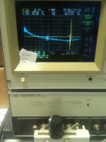
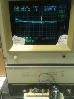
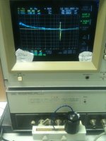
Did a quick test of an electrolytic, 1500uF/200V, on the analyzer. First no leads, 6inches seperated leads, and finally same leads twisted.
No leads resonance at about 27kHz.
6inches of wire resonance little above 8kHz.
6inches twisted wire resonance about 12kHz.
It still has capacitance above resonant frequency, but does it supply current? I am not quite sure myself, but obviously we want short leads to where we want to decouple.
Attachments
this is what you saidAndrew, you're cracking me up. That is exactly what I said above, then you started argueing.... well, let's leave it at that...
because most people don't know that the really important path is rail-to-rail, right at the chip.
1500uF is a fair medium sized electrolytic.
3 to 10times that is typical of main smoothing capacitors in Power Amplifiers.
You are measuring a resonance of 27kHz and yet we often see Members stating that modern big electros are getting close to 100kHz resonance.
Are they talking through their hats?
or are some electros so much different from others?
I find fysical size dominates regarding resonance frequency. They simple are more inductive as they get larger, and the resoance freq goes down. I just testet a huge screw terminal type Panasonic 160V 56000uF lytic. It's about 9cm in diameter and 22cm tall. It's resonance is about 2kHz. The analyser is having trouble getting steady readings, keeps jumping up and down for each new sweep. Above this frequency the capacitance shows up as negative. The ESR is only a few mohms even way above resosnance, it doesnt really climb till we get to about 1MHz. That must be the ESL starting to take over.
The low resonance frequency must be because of the large amount of capacitance as well as the inductance, since the F-res is a product of both (square rooted) in the denumerator.
The low resonance frequency must be because of the large amount of capacitance as well as the inductance, since the F-res is a product of both (square rooted) in the denumerator.
- Status
- This old topic is closed. If you want to reopen this topic, contact a moderator using the "Report Post" button.
- Home
- Amplifiers
- Power Supplies
- Capacitance vs Ripple current