Hello
I have recently completely rebuilt the left channel amp board of my Nikko 1415 receiver
I replaced all components due to a catastrophic failure of the shorted outputs and drivers , burnt resistors etc...
The previous tech had installed drivers in the VA stage that were rated at half the voltage required and possibly fake outputs.
I have replaced the parts with parts recommended by the great people on audiokarma where necessary
I have turned it on following all safety measures and using my old variac. No smoke looks good, comes out of protect ..... one problem so far
I check the voltage at the test points to adjust for 18.0 mv on the bias circuit
And i cant get it to respond - It just jumps up and down thumping
I hooked up some speakers(test pair(cheap but good ) and i hear and see a strong pulse like a heart beat out of the side in question about 80 beats per minuet
Any pointers for me to check? I am applying no signal to the input as per instructions to set bias pot. And amp is not going into protect mode yet. Aslo no dc at speaker terminals
The pulse is about 700mv ac at speaker terminal
Thank You , I am sorry to place such a burden on others , but I am lost
I will post pics of finished amp as soon as finished
I find I make a lot of cold solder joints, even with this new 35 W iron. Old steel lead components get a coating of oxide on them, and rosin solder doesn't stick well. Scraping the surface with a screwdriver before soldering helps.
One detects these problems with a DVM, looking for impossible states. Component leads at two ends of a trace at different voltages. Diodes dropping more than 0.7 v forwards. Resistors dropping more voltage than the wattage would allow (v= sqrt(P/R)). Capacitors with the same DC voltage on both ends.
Look for these things, you might find your errors. Good hunting.
Expect other people in the forum to think alike but few of them will spent time on this even though intention is otherwise as a starting point .
1) the Data provided do not support a conclusion
2) Why don't you take your question to the great people on audiokarma ?
3) i will have to presume that the question has been already placed there with no results but this doesn't come as a surprise to me
4) I could have a better opinion if i had a list with the replaced parts
5) Are you able to tell if the parts you have are at least original ?
in reality
--from experience i may tell you that what you listen is a wrongly oriented part can be a capacitor but can also be a poor choice or wrong choice of a semi
--Then again a unit that old might suffer from a number of issues except the power amplifier . You need to make sure that the problem is coming from the amplifier unit and is not injected to the amplifier by the preamplifier
--If as said this is only happening to the one ch the best way is to measure in cross reference with the working one but obviously if the choice of semis in the working ch is poor or wrong expect results to be very very wrong ...
Provide more data about the problem , provide a list of replaced semis and may we get somewhere
Real regards
Sakis
I find I make a lot of cold solder joints, even with this new 35 W iron. Old steel lead components get a coating of oxide on them, and rosin solder doesn't stick well. Scraping the surface with a screwdriver before soldering helps.
Making sure all parts of any joint are clean is a MUST. A screwdriver? You'd get better results with a bit of fine emery paper.
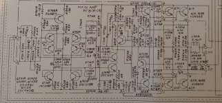
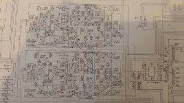
schematics and replacements for NIKKO 1415
Here is the schematic of the Nikko 1415
Ive replaced all components
I replaced the
Q701,702,704,705 = 2SA941 BL with 2SA970 BL
Q706,Q707 = 2SC2088 BL with 2SC2240 BL
Q708 = 2SA817 with same
Q709 =2SC1627 with same
Q710 =2SD381(2) with 2SC2073
Q711 = 2SC1627 with same
Q712 = 2sc945 with KSC945
Q713 = 2SA733 WITH KSC733
Q714 = 2SD381(2) with 2sc2073
Q715 = 2SB536(2) with 2SA940
I also replaced diodes
D701 VD1212 with 2 1n4148 in series
D702 VD1212 with 2 1N4148 in series
Attachments
I am getting lower voltage readings than in the manual. At the collectors of the input pairs about 6-7 volts less.
At the reguator input to the maun amp about 8-10 volts low. At the regurator output to the amp the voltage is the same about 10 volts low
I am not sure if this could lead to the problem with the bias voltage not being adjustable , or the constant pulse at the output
Also I am now seeing a 700mv-1.5v ac pulse at the output
And a dc 50 - 150mv pulse as well. The same pulse with both voltages ac and dc
The readings move so fast its hard to get a accurate reading
A good visual check is a good place to start.
Unsoldered or cold solder joints and solder shorts.
Components in wrong way around.
If you have been recommended transistors I would check the datasheets between original parts and substituted parts. Faster parts can sometimes cause oscillation.
I got caught out with old Maplin amp. I fitted new transistors of same type but the amp oscillated at a low frequency. Turned out the newer transistor had a much higher gain causing the problem. I had to tweak the VAS capacitor to fix it.
You've done a huge amount replacing all those semis.
Here is what I would do...
1/ Measure the volt drop across the original D701 and D702 and see how they compare to your series 4148's (measure across those in the good channel for a comparison). These are critical components in that they determine a reference voltage for the cascoded VAS stage and also determine the Vbe multiplier characteristics.
2/ With no load attached what is the DC offset of the repaired channel (voltage across speaker sockets) ?
3/ What is the recommended bias for this amp ? With no load attached, does the bias vary smoothly and have a good range on the preset. i.e. can you reduce it to zero and then take it over the recommended setting with no jumps or weird behaviour.
If all that checks out OK, what happens if you then connect a speaker. Does it start doing this pulsing thing again ?
Lower voltage than specified is a suspect
check wiring of the specific amplifier for any errors also check ground connections very carefully
keep in mind that for some circuits the shield of the input stage provides also ground for the input first stage
Any mistake in the connections there cane take you to all shorts of problems
Kind regards
Sakis
Cant adjust bias! but fixed previous problem of thumping
The motorboating is gone, Thank You for the help
Turns out the problem was probably a bad ground. I re soldered all parts and re tied all connections . Cleaning and sanding any possible connection point.
Now I can not adjust the Bias - The bias at the test points reads 20mv, when i first turn on, until the relay clicks and the amp is out of protect mode. Then the bias voltage drops to 1 - 2 mv But i can not adjust it. it does not respond to adjusting the 1k bias pot
The service manual call for 18mv
Also now there is a buzzing not very loud but definitely audible .
The buzzing goes away with volume down and comes back as soon as i turn volume up
Now I can not adjust the Bias - The bias at the test points reads 20mv, when i first turn on, until the relay clicks and the amp is out of protect mode. Then the bias voltage drops to 1 - 2 mv But i can not adjust it. it does not respond to adjusting the 1k bias pot
Something is amiss there. Have you got speakers connected ?
If the voltage across the test points alters when the relay connects then that points to there being both a DC offset voltage at the output and also a load connected (that can draw current due to that offset)
With NO speaker attached check that the DC voltage from ground to the amp output is near zero.
Also check that the voltage between C and E of Q711 varies as you turn the preset.
What voltage can you achieve between C and E and how does that compare to the good channel ?
Verify all voltage present according to the schematic and measure in reference with the other ch .( output stage and driver area )
Check very carefully emitter resistors in the output stage 739,40,41,42 for open
Check very carefully 4.7R 729 730 base stopper resistors for open
Check very carefully load resistors on drivers 726 ,728
Check or replace as a precaution vbe multiplier Q711
Check bias trimmer for proper and linear operation ( might be black down under )
Finally use a heat gun or anything similar to see if warming up the drivers will restore or change the bias if so that will mean that any of the drivers has a mechanical failure and goes open when cold or warm ( situation impossible to trace with a DVM and with the transistor outside the circuit )
The above might working the other way around IE with a zero freeze spray
Kind regards
Sakis
Gmorning Mooly !! here we are again !!!
Early start ??? get your self a cup of coffee before you start ... forget the offset if there was any protection that is common for both amps will trace it and will not start the amp Relay clicks !!!
@trebolo if you dont manage after all please place keyboard and mouse next to the amp and either me or Mooly will get it fixed for you ...
Having a bit of fun in a Sunday morning
Kalimera to all of you !!
Kind regards
Sakis
Early start ??? get your self a cup of coffee before you start ...
forget the offset if there was any protection that is common for both amps will trace it and will not start the amp Relay clicks !!!@trebolo if you dont manage after all please place keyboard and mouse next to the amp and either me or Mooly will get it fixed for you ...
Having a bit of fun in a Sunday morning
Kalimera to all of you !!
Kind regards
Sakis
- Status
- This old topic is closed. If you want to reopen this topic, contact a moderator using the "Report Post" button.
- Home
- Amplifiers
- Solid State
- Cant adjust bias on rebuild? Please help?