To test components properly, they should be out of circuit. This is especially so for the bridge rectifier diodes - otherwise you will get incorrect readings as the transformer windings will be "shorting" them.
Almost certainly the SAP15 transistors will have failed. They have a known weak point which is why Sanken discontinued their manufacture... and the poor heatsinking of these Cambridge amps exacerbates the problem.
Almost certainly the SAP15 transistors will have failed. They have a known weak point which is why Sanken discontinued their manufacture... and the poor heatsinking of these Cambridge amps exacerbates the problem.
Download service manual for CA A500 below, it's almost the same as for CA A5...you will need it for reference/repair.
BTW, don't assume output transistors are completely gone, maybe only internal 0,22R emitter resistor are gone, it happened before.
If those resistors have blown, the transistor package will have been compromised (even if you cant see the crack). The transistors need replacement therefore.
My experience of these amps when they have been "partied" is the following. Part numbers are for the left channel:
* The SAP15's fail. Sometimes catastrophically, you can see holes in them.
* Often the bias pot (RV201) fails, and so does the capacitor (C238) across it.
* The VI limiting components often get damaged - Q207, Q207, D202, D205 and associated resistors
* Sometimes the VAS stage is damaged - Q206, Q210, Q211 and associated parts.
Use the service manual for the Cambridge Audio A500 - the amps are nearly identical, the power stage is.
I don't recommend fitting SAP15/SAP16 as replacements - they are obsolete now, can be tricky to get (leading to you looking at eBay and getting fake parts), and have the same problem.
Instead you can fit STD03 transistors - these are the same except they don't have the internal emitter resistors. You can then fit some external 3W 0.33 ohm resistors in place of them. This has proven to be reliable in my experience, though still doesnt make Cambridge amp's "party proof" !
Can I do that in circuit?
Thanks
Yes, a short will always show up in circuit.
Edit... just seen Jaycee's reply
") if you are not sure then isolate one end but a dead short will always show assuming your meter can resolve low resistances.
if you are not sure then isolate one end but a dead short will always show assuming your meter can resolve low resistances.Yes, a short will always show up in circuit.
Edit... just seen Jaycee's reply
My experience is that multimeter continuity test can be unreliable.. it's easier just to pull the diodes to test them. You also have the possibility of the PSU caps or diode snubber capacitors giving false readings.
I havent actually ever found the bridge diodes to have failed in one of these amps.. the SAPs give up first
I managed to take one NY transistor out yesterday. Only one connection, S-E works and my DMM reads ~0.2Ohms. The rest of the connections either show infinity or high resistance. The diode function on pins B-D reads inf/high resistance both ways.
The bridge rectifier (if that's what it is.. the 4 components right next to the fuses) show no continuity and a resistance in the Mega Ohm region.. but that may be something to do with the capacitors being crap right?
I measured the resistance across both the fuse sockets and the left side read almost twice the resistance value as the right.. No idea why.
I'm still waiting for my T4A fuses and the new capacitors in the post so I'll report some more data when I get them.
I measured some resistors and some of them were also in the high KOhm / Mega Ohm region. Is it normal to have resistors of such a high value?
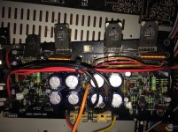
It's the small green resistors that measured really high.
Also the large green resistors have low enough resistance the continuity beeps across it. The resistors that are the same size (largest) but more brown have high resistance also. And there continuity function doesn't beep.
Could it be that it is measuring a sum of resistances in the circuit?
You can also see the leaked capacitor fluid in this picture.
Attachments
Last edited:
The diodes in the bridge appear to be OK from your readings. A shorted device would show (and that is how they would fail).
All other resistance checks need to have the parts isolated (unsoldered at one end) in order to stop interaction with other parts in the circuit. Also any small residual charge on the caps can confuse most DVM's when trying to do resistance checks.
As long as you have a bulb tester in place then you can temporarily link out the two secondary fuses to allow you to work on the amplifier. There is no safety risk because the bulb limiter threshold is way below the rated 4 amps, and of course we are dealing with the secondary side of the transformer.
Can someone explain how to fit the mains bulb tester?
So I have a 60W bulb with the bulb socket and mains wires attached to it.
Where on the attached pictures would I attach the wires from the bulb?
I have disconnected all of the other pcb's that attach to the main pcb via plastic connectors. Is this ok to do? I'm going to remove all the Sap15's before I start testing with the bulb.
The bulb simply goes in series with the live mains feed.
Disclaimer if you are not confident doing this then don't do it.
If your bulb tester is 'safe' and constructed correctly and you are happy with it then the easiest method of connection is to remove the mains input fuse and solder the bulb across the empty fuse holder.
Disclaimer if you are not confident doing this then don't do it.
If your bulb tester is 'safe' and constructed correctly and you are happy with it then the easiest method of connection is to remove the mains input fuse and solder the bulb across the empty fuse holder.
The filament of a bulb is non linear.
Take a cold bulb and measure its resistance on your meter. Now calculate the current if you applied say 240 volts to the bulb. Quite a lot isn't it ?
Now calculate the wattage using the formula of current squared multiplied by the resistance.
A bit more than 60 or 100 watts as marked on the bulb.
The reason why is because the bulb filament increases its resistance dramatically as gets hot and we use that to our advantage with the bulb tester. If the amp draws little current (no faults) then it receives nearly the full mains voltage because the current is not enough to heat the bulb and so the resistance of the filament is low.
If there is a fault then the bulb current increases, the filament gets hot and that both limits the overall current and consequently the overall voltage applied to the amp.
https://www.google.co.uk/search?q=b...ei=taoRWZnQFMiVgAbHhr0I#imgrc=8lo0nlTOZID3iM:
from decibel dungeon about half way down
http://www.decdun.me.uk/gaincloneFAQ.html
Buy some bulbs of various wattage from 25W to 150W
I always start with the lowest and if the equipment draws a bit too much current the bulb lights up.
I check that the polarities of the Low Voltage DC are right and then swap to a slightly bigger bulb and check polarities again.
Last edited:
do not remove the capacitors. They will get a check when you measure the ripple voltage.
just disable the 4 output transistors.
I see the four big green resistors. What do the colour codes tell you?
I can see that the left of each pair is discoloured to brown in the middle. That indicates they have been massively overheated. That may tell you which of the output transistors is blown.
just disable the 4 output transistors.
I see the four big green resistors. What do the colour codes tell you?
I can see that the left of each pair is discoloured to brown in the middle. That indicates they have been massively overheated. That may tell you which of the output transistors is blown.
- Status
- This old topic is closed. If you want to reopen this topic, contact a moderator using the "Report Post" button.
- Home
- Amplifiers
- Solid State
- Cambridge audio A5 blowing fuses help