Hi all,
I have been given a Cambridge audio A5 amplifier that is faulty.
Reported Failure:
Apparently it blew during a party. Probably due to the poor heat sink.
Failure:
Blows both T4A fuses blow on each channel on power up. The T2A power supply fuse remains intact.
Observations:
-Has leaked 2200uF 50v capacitors. But no bulging or disfigurement.
-No other signs of burning or damaged components but that is only a visual inspection.
-Although there is one resistor that looks more brown, however it is exactly the same on both channels.
-No burn marks on the Pcb
-No obvious burns in other components
Questions:
It has sap15 ny and py transistors. Is it worth unsoldering them and check the resistance through the diode both ways? Or any other pins? It had 5 pins.
Also, could it be possible the thermal fuse has blown in the transformer? And is there an easy way to check this?
Is there easy way of checking components when they are in circuit?
Parts:
I've bought some replacement 2200uF 50v 105 Deg capacitors so slightly upgraded from the 85deg ones in it.
And T4A fuses
Any help or suggestions are welcome. I have a DMM and no other testing equipment. Physics degree but not a lot of electronics knowledge
Attachments
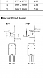
If someone could tell me a good way of testing these SAP15 transistors that will be a great help. I've attached a circuit diagram of the SAP15's.
Say if I test between pins B and D both ways. E.g for NY type: B-D should be low resistance and D-B should be high/inf.. Am I right in thinking that?
Then I could test B-E? The resistance should be 70.22Ohms? But that depends if the switches are open right?
Does anyone have a good method of testing these with a DMM?
Also, I have bought the same but higher T capacitors.. should I have upped the capacitance or voltage? Or is it good that I left them with the original values?
Cheers
Failure mode of the output transistors will almost always be a reading of either a short or a very low resistance between C and S.
For the NPN devices you should get a reading of 'infinity' between C and S when your red meter lead is on C. For PNP device the black lead should be on C.
For the NPN devices you should get a reading of 'infinity' between C and S when your red meter lead is on C. For PNP device the black lead should be on C.
Failure mode of the output transistors will almost always be a reading of either a short or a very low resistance between C and S.
For the NPN devices you should get a reading of 'infinity' between C and S when your red meter lead is on C. For PNP device the black lead should be on C.
Say... a current (e-) travelling from C to S (NY type) and you measure using a DMM... it should read inf due to the switches being open? If it reads low resistance / short it means the switches are permanently closed and so not functioning correctly.
Is that the right thinking?
Is that the right thinking?
Yes.
The basic test is using a meter on ohms or diode range. If the device is short circuit (or nearly so) then it will show as such while testing in circuit.
For an NPN device and with a positive test voltage on the collector then no current should flow between C and E. That is what this basic test proves.
If the reading is low then the device has failed.
Oh bugger. Just looked back at your pics. The PSU is on board after the fuses.
What follows cannot be applied to your transformer.
You can only measure the Vac direct from the transformer after the fuses have been pulled.
You can measure your transformer.
Pull the two secondary fuses.
Find the two speaker terminals that are connected. Use the continuity function (low ohms might have a beeper for this). These will also be connected to the amp's Power Ground.
Attach the black DMM probe to one of these speaker terminals.
Power ON via a Mains Bulb Tester. The Bulb will probably flash medium bright and then turn off. Measure the voltage using the red probe at each of the secondary fuses. You should see ~ +45Vdc on one and ~ -45Vdc on the other.
Now set your DMM to 200Vac.
Measure to the two fuses. If they read less than 1Vac, then switch to 20Vac and measure again.
If that measures less than 0.1Vac, then switch to 2Vac. That should now give you an approximate ripple value on the smoothing capacitors.
You can only get down to this setting if your DMM blocks the DC voltage and allows it to read the remaining AC on the supply rails. Some DMM cannot do this. If you read a high Vac, then stop here and come back with your results. There is a way to block the DC and allow the DMM to give useful results.
If it reads less than 0.02Vac, then switch to 200.0mVac and measure again.
Take those final readings and multiply by three. That gives you a Vpp reading for the ripple on the DC supply rails. Because the fuses have been removed the ripple should be very low.
Very low mVac and ~+-45Vdc indicates that the transformer and PSU have not been damaged.
Last edited:
Oh bugger. Just looked back at your pics. The PSU is on board after the fuses.
What follows cannot be applied to your transformer.
You can only measure the Vac direct from the transformer after the fuses have been pulled.
You can measure your transformer.
Pull the two secondary fuses.
Find the two speaker terminals that are connected. Use the continuity function (low ohms might have a beeper for this). These will also be connected to the amp's Power Ground.
Attach the black DMM probe to one of these speaker terminals.
Power ON via a Mains Bulb Tester. The Bulb will probably flash medium bright and then turn off. Measure the voltage using the red probe at each of the secondary fuses. You should see ~ +45Vdc on one and ~ -45Vdc on the other.
Now set your DMM to 200Vac.
Measure to the two fuses. If they read less than 1Vac, then switch to 20Vac and measure again.
If that measures less than 0.1Vac, then switch to 2Vac. That should now give you an approximate ripple value on the smoothing capacitors.
You can only get down to this setting if your DMM blocks the DC voltage and allows it to read the remaining AC on the supply rails. Some DMM cannot do this. If you read a high Vac, then stop here and come back with your results. There is a way to block the DC and allow the DMM to give useful results.
If it reads less than 0.02Vac, then switch to 200.0mVac and measure again.
Take those final readings and multiply by three. That gives you a Vpp reading for the ripple on the DC supply rails. Because the fuses have been removed the ripple should be very low.
Very low mVac and ~+-45Vdc indicates that the transformer and PSU have not been damaged.
Thanks for you replys. A couple of questions. Do you mean pull the fuses as in remove them from the system? Or something else?
Also what is a mains bulb tester? Is this something I'd have to buy?
And the speaker terminals that are connected.. are there only two that are connected? And connected to what exactly? Find the terminals that are connected to the power ground?
Thanks. Sorry for my uneducated questions.. I don't have much electronics knowledge but I'm learning with this process.
the two secondary fuses are on the PCB.
Remove these from their holders. That will probably disconnect everything from the transformer.
There may be traces underneath that make extra connections, but I can only see the big Power Diodes to rectify the AC, indicating that the fuses break everything.
Look up Mains Bulb Tester, some call it Dim Bulb and a few other names.
You build it from just four household items.
A plug top, a socket outlet, a mains bulb holder and a tungsten filament mains bulb to fit that holder.
Only two speaker terminals are connected. They are probably coloured Black to indicate the speaker Return terminals. These should be connected to the Power ground, unless there is a speaker delay/protection fitted into the Return route. The speaker Returns save you having to find the Power Ground which may not be accessible from the top side or available but not labeled.
Last edited:
There is another testing alternative.
Disconnect the 4 main Power Transistors' Collector (C) and the Base (B) leads from the PCB. But I see they are soldered in with very short leads. This may prove to be impossible without damaging either the PCB or the transistors.
These 8 leads will effectively remove the output stage from the amplifier and allow the amp to power ON without blowing the fuses. The amp won't work, because the Negative FeedBack (NFB) has also been disconnected as well as removing the output stage. But the other parts will become powered and live and with luck these may not be damaged.
This will allow the PSU ripple to be measured. It will be slightly higher because the half amp that is still connected draws some current and this increases the ripple slightly.
I'm probably going to have to remove/replace the power transistors anyway so that method may be a better option.
If I disconnect those 8 wires do I go through the same process as described before? Read voltage across each fuse socket (-/+45dc).. then setting DMM to 200Vac and reduce by factor of 10 each time.
This method requires fuses in the sockets right? I will have to wait until my fuses arrive later in the week to test this method.
Thanks
the fuses are connected before the PSU.
You need to measure the DC at the PSU rather than at the fuses.
I suspect there are points where you can probe safely. Remember the black is already semi-permaently connected to one speaker Return terminal. You only have to be VERY carefull in placing the red probe to get a voltage reading.
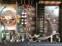
Can you post a close up of the amp PCB? Maybe daylighting might help with focusing.
You need to measure the DC at the PSU rather than at the fuses.
I suspect there are points where you can probe safely. Remember the black is already semi-permaently connected to one speaker Return terminal. You only have to be VERY carefull in placing the red probe to get a voltage reading.
Can you post a close up of the amp PCB? Maybe daylighting might help with focusing.
Oh, I remember you said the secondary fuses both blew and that the Mains fuse did not blow.
Secondaries were T4A?
What fuse is fitted in the primary? (bottom left corner) and pull the mains plug before you touch it !!!!
Without a soft start it cannot be close rated and will probably be either T1.6A or 2A
Does the external labeling give any clues?
Secondaries were T4A?
What fuse is fitted in the primary? (bottom left corner) and pull the mains plug before you touch it !!!!
Without a soft start it cannot be close rated and will probably be either T1.6A or 2A
Does the external labeling give any clues?
the fuses are connected before the PSU.
You need to measure the DC at the PSU rather than at the fuses.
I suspect there are points where you can probe safely. Remember the black is already semi-permaently connected to one speaker Return terminal. You only have to be VERY carefull in placing the red probe to get a voltage reading.
Can you post a close up of the amp PCB? Maybe daylighting might help with focusing.
Ok thanks Andrew. Are there any safe bets when probing a psu? Or any particular component to target?
Oh, I remember you said the secondary fuses both blew and that the Mains fuse did not blow.
Secondaries were T4A?
What fuse is fitted in the primary? (bottom left corner) and pull the mains plug before you touch it !!!!
Without a soft start it cannot be close rated and will probably be either T1.6A or 2A
Does the external labeling give any clues?
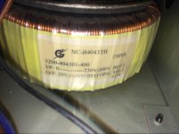
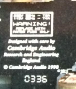
It says 230v 50Hz T4A
115v 60Hz T2A
The primary is T2A
If it hasn't already been mentioned then its worth checking the bridge rectifier for shorts.
I can make out 115v 4T in the first picture, can't deciper the one above but imagine its 2T.
So the bridge rectifier should be 115v across it? I don't know where the bridge rectifier is to be honest.
Download service manual for CA A500 below, it's almost the same as for CA A5...you will need it for reference/repair.
BTW, don't assume output transistors are completely gone, maybe only internal 0,22R emitter resistor are gone, it happened before.
BTW, don't assume output transistors are completely gone, maybe only internal 0,22R emitter resistor are gone, it happened before.
Attachments
- Status
- This old topic is closed. If you want to reopen this topic, contact a moderator using the "Report Post" button.
- Home
- Amplifiers
- Solid State
- Cambridge audio A5 blowing fuses help