Dr, is it possible to share pcb for calor ampl.?All my knowledge and experience are futile value if they went with me one day under the ground, and I have not conveyed to others!
Best regards .
Thimios.
Last edited:
O sorry Dr, just now i see this.Yes thimios, write directly on docacacak{at]gmail(dot)com
Thanks.
Regards.
Thimios.
Well said ...All my knowledge and experience are futile value if they went with me one day under the ground, and I have not conveyed to others!

Would you mind if I derived from the calor to make a high power version
"slew" IPS ?
A question ... there seems to be 2 FB loops , one VFA/one CFA.
Does this split any voltage gain between the two stages ?
I was thinking of using a cheap standard dual op-amp , use one for servo ...
one for the main "deal" (amp). Also , standard hawksford as VAS.
OS
small progress in calor gold.
You must compare calor/eyesee . 2 "tricks" can get the same result.
OS
Now you need to reveal trick detailsYou must compare calor/eyesee . 2 "tricks" can get the same result.
OS

Last edited:
That's before first test fire!small progress in calor gold.
I must mention that i haven't all appropriate parts so some parts are for test conditions ONLY.
Attachments
Last edited:
That's before first test fire!
I must mention that i haven't all appropriate parts so some parts are only for testing conditions.
mean machine!
Can't wait... I hope I can hear the progress soonThat's before first test fire!
I must mention that i haven't all appropriate parts so some parts are for test conditions ONLY.
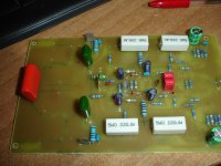
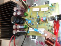
CALOR GOLD
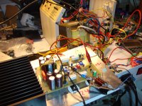
First test successfully ended.
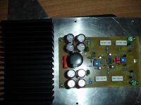
First time, amplifier tested at +/-24v from two regulated power supplies.
Second test with two transformers ,one +/-16v and other +/-8v in series.
All under control.
All small signal transistors BC550C,560C.
Out fets IRFP240,9240.
Sorry Dr.but i have these on hand now.
Tomorrow i will have a small listening test.
Some pictures from first test.
I guess it is not permissible to show the copper side.
First test successfully ended.
First time, amplifier tested at +/-24v from two regulated power supplies.
Second test with two transformers ,one +/-16v and other +/-8v in series.
All under control.
All small signal transistors BC550C,560C.
Out fets IRFP240,9240.
Sorry Dr.but i have these on hand now.
Tomorrow i will have a small listening test.
Some pictures from first test.
I guess it is not permissible to show the copper side.
Attachments
I guess it is not permissible to show the copper side.
I hope you won't do that. Thank you!
I hope you won't do that. Thank you!
Why? Earlier you encouraged folks to build and test this amp.
Ok Dr.I hope you won't do that. Thank you!
Just a clarification. Two transformers are.1)2x16v a.c, 2)2x8v a.c.So the d.c (after rectifiers & series connection) is 2x31v d.c
Terry you can send mail to Dr. ,he will give you everything that is necessary.
Last edited:
Why? Earlier you encouraged folks to build and test this amp.
Because of such things... read from first post.
http://www.diyaudio.com/forums/solid-state/195351-80w-hybrid-audio-amplifier.html#post2686578
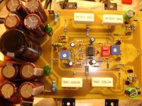
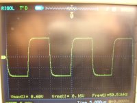
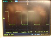
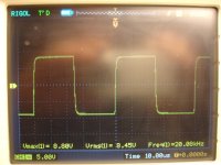
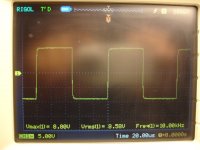
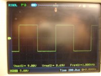
calor gold measurements.
Power suplly +/-30v
33.000uf/rail
R dummy=7R
Idle current =800mA./pair
1v RMS input give 20v RMS out./7R dummy=26db
20v RMS/7R=57W RMS just before clip.(1000Hz)
Power suplly +/-30v
33.000uf/rail
R dummy=7R
Idle current =800mA./pair
1v RMS input give 20v RMS out./7R dummy=26db
20v RMS/7R=57W RMS just before clip.(1000Hz)
Attachments
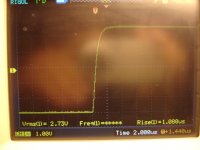
It looks almost like good amp...
An externally hosted image should be here but it was not working when we last tested it.
- Home
- Amplifiers
- Solid State
- Calor amp 40 Watts Class A