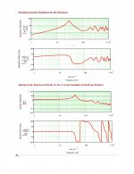
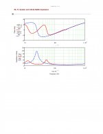
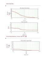
The tuning isn't really doing anything currently - you wont hear the hump in their current state as the roll off is around 20db at 40hz.
Room acoustic is solveable - a local home cinema room company for a price will come and do a survey and tell me how much to fix it with lots of foam etc.
I am glad i am being the example of how not to build a MLTL.
Whats happened to yours Buzz - was wanting to see if yours worked first time!
Room acoustic is solveable - a local home cinema room company for a price will come and do a survey and tell me how much to fix it with lots of foam etc.
I am glad i am being the example of how not to build a MLTL.
Whats happened to yours Buzz - was wanting to see if yours worked first time!
Doubtful, as I know less than you and depending heavily on modeled response. My current choice is here. screwed up start point of port, but doesnt change much. I like the idea of downward firing port, but it has been suggested that this not feasible without significant lift off the ground to reduce floor interaction.
http://www.diyaudio.com/forums/multi-way/91372-altec-lansing-95.html#post3535052
http://www.diyaudio.com/forums/multi-way/91372-altec-lansing-95.html#post3535052
Well, everything I’ve seen still comes up a leak and to answer my earlier seeming conundrum, I’d forgotten that this is a folded pipe, so a leak between the two pipe lengths around the divider board satisfies it.
Also, if the divider board isn’t long enough, i.e. doesn’t preserve the area expansion around the bend, it can at least partially be the cause when the driver is at the top of the bend.
GM
Also, if the divider board isn’t long enough, i.e. doesn’t preserve the area expansion around the bend, it can at least partially be the cause when the driver is at the top of the bend.
GM
Last edited:
I like the idea of downward firing port, but it has been suggested that this not feasible without significant lift off the ground to reduce floor interaction.
Define 'significant'. IME, the larger the cab's base area, the less gap required due to a greater slot radiating area.
GM
GM,
Thanks for the answer. The port would be 6" in diameter and base would be appx 24"x25". Sim looks good to my eyes, being bested only by much larger cabinets or ones with driver positioned 1/2 down length. Talking about ideal, positioning the driver 1/2 way down the TL is quite shocking in what it does, but practical layout is difficult in my mind.
Thanks for the answer. The port would be 6" in diameter and base would be appx 24"x25". Sim looks good to my eyes, being bested only by much larger cabinets or ones with driver positioned 1/2 down length. Talking about ideal, positioning the driver 1/2 way down the TL is quite shocking in what it does, but practical layout is difficult in my mind.
You're welcome!
FWIW, I get a 2.55” slot assuming there’s at least 6.68” clearance to any walls, otherwise it would become an empirically arrived at gap for me, but historically I use slot loading to further mass load the vent or make up for a too short cab acoustical pipe length, so no experience trying to find a 2pi loading solution to a 1.0 or 0.5pi boundary condition or even know if there’s one in theory.
Hmm, to my way of calculating it, ~half way is only 'ideal' in a golden or acoustic ratio cab or typical expanding TL [ML-horn, AKA MJK's ML-TQWT project].
Usually not difficult if folded, but folk's generally not tolerating a wide baffle severely limits design options too much to make it practical.
GM
When you say 2.55" slot, is this assuming no internal port length and using floor to create this slot.
Here is 30% driver placement
Here is 30% driver placement
Attachments


Here is 50% of line length. Sorry Vinylvalves, if GM helps me sort this, ill happily let you get a laugh or two at my expense.
Attachments

When you say 2.55" slot, is this assuming no internal port length and using floor to create this slot.
??? It's clearance to a parallel boundary [floor in this case] as a function of the vent diameter and the speaker 'baffle' perimeter [bottom in this case].
GM
Here is 50% of line length. Sorry Vinylvalves, if GM helps me sort this, ill happily let you get a laugh or two at my expense.
Sort what??? Regardless, why are you posting it here?
GM
A sectio through the test cabinet showing how the speaker is located with respect to the fold.
OK, you did it right, the other sketch implied the divider board was truncated much lower, yet the cab is measuring like a too large reflex.
GM
Sort what??? Regardless, why are you posting it here?
GM
Thanks for the advice, GM. That's what I meant by sorted. Sorry again vinylvalves. I'll give mine a shot and see how it goes. I'll continue to follow your build and wish you good building.
As i truncated the divider board as i should - where to do next, to get the LF extension.
I could fit the supravox 285gmf's i have to see what they do in the cabinet- will also rule out (hopefully ) one of my throughts that the driver is leaking some how. I have checked the surround on the altecs and the goop seems to be distrubuted all the way around. I do feel i am starting to see there will be no solution to this.
I could fit the supravox 285gmf's i have to see what they do in the cabinet- will also rule out (hopefully ) one of my throughts that the driver is leaking some how. I have checked the surround on the altecs and the goop seems to be distrubuted all the way around. I do feel i am starting to see there will be no solution to this.
This happened on a big TH build over on AVS. A guy assembled a DSL DTS10 kit that was all nicely routered out for all the divider boards, but there was some fitting issues, winding up kind of forcing the big side panel to fit.
Unfortunately it made zero 'sub' bass till he removed the mass quantity of screws and somehow broke the glue joints loose enough to pry it off, caulk everything, etc., you see where I'm headed here.........
GM
Unfortunately it made zero 'sub' bass till he removed the mass quantity of screws and somehow broke the glue joints loose enough to pry it off, caulk everything, etc., you see where I'm headed here.........
GM
Loud and clear - will check for leakage paths around the divider board, with the amount of glue i used and that it sits in a ploughed dado slot, will make it difficult to remove so will caulk if necessary. I dont think i have any leakage paths but will check. Suppose a pressure test of both halves may be the only way to be numeric regarding the leakage rates.
Highest pressure is at the closed end, so with the vent on the opposite side, this area would seem to be the most likely, but there's enough 1/4 WL action in a 61" line to lose most of it in seemingly sealed joints, leaking front to back except around/at Fb when both are pressurized, which would explain the peaking at Fb.
Hope this does it since without being there I can't think of what else to try other than doing a pressure check of the driver, but assuming the measurements are valid, which they seem to be, all 'roads' lead to a leak.
This can be like chasing down a slow tire leak sometimes........
GM
Hope this does it since without being there I can't think of what else to try other than doing a pressure check of the driver, but assuming the measurements are valid, which they seem to be, all 'roads' lead to a leak.
This can be like chasing down a slow tire leak sometimes........
GM
Drat! I was so wore out last night when I posted that I just noticed you have other drivers to try, so try them first since I just did a Petite Onken sim with your driver’s specs and couldn’t come close to matching it regardless of the output impedance, so could very well be a driver leak.
Hope you haven’t started tearing it apart yet.
GM
Hope you haven’t started tearing it apart yet.
GM
GM,
Thanks for the answer. The port would be 6" in diameter and base would be appx 24"x25". Sim looks good to my eyes, being bested only by much larger cabinets or ones with driver positioned 1/2 down length. Talking about ideal, positioning the driver 1/2 way down the TL is quite shocking in what it does, but practical layout is difficult in my mind.
I found something around 4:9 to 9:20 placement ratio seems to be closer. Tweaking this position could completely smooth out the 2nd harmonic null. Port placement was always best around 2.5-3" from the base. < Think this is very critical. Folded up this could be anywhere. The same is true of what GM does with floor loading through the base. Effectively the same thing, but would add that GM's suggestion is best for max port gain.
VV,
In your sketchup is the port a hole simply through the wood or had length? A simple hole has a very low and broad Q. Placement is not close enough to the bottom and thus could be influencing your results significantly. The line length determines the tuning frequency. Placement of the port along that length effects what frequency your tapping. Port length should be tuned to driver resonance, which would make it rather long for the area used. Simplest TL example is a flute. It's an open ended transmission line tuned to it's fundemental by overal length. Keys opening/closing low Q ports along it's length produce the various notes.
Last edited:
- Status
- This old topic is closed. If you want to reopen this topic, contact a moderator using the "Report Post" button.
- Home
- Loudspeakers
- Multi-Way
- Cabinet Design for Altec 414z's