Hi all,
i published a C-library to generate commands to control a MUSES72323.
Link to sources
It has no dependencies besides C compiler and library. I'm using it in a project utilizing a PIC18, programmed via MPLABX IDE and compiled by XC8.It should be fairly easy to integrate different Microcontrollers (Arduino, RP2040 etc). To do so you just have to provide a platform-specific
I hope it helps to realize some of your projects.
If you have any questions please feel free to ask.
Edit: removed reference to SPI as library does not implement actual GPIO-pin-logic for transmission, but only bit-pattern generation.
i published a C-library to generate commands to control a MUSES72323.
Link to sources
It has no dependencies besides C compiler and library. I'm using it in a project utilizing a PIC18, programmed via MPLABX IDE and compiled by XC8.It should be fairly easy to integrate different Microcontrollers (Arduino, RP2040 etc). To do so you just have to provide a platform-specific
send(muses_command) functionI hope it helps to realize some of your projects.
If you have any questions please feel free to ask.
Edit: removed reference to SPI as library does not implement actual GPIO-pin-logic for transmission, but only bit-pattern generation.
Last edited:
I can't make any sense out of Your source and header files, and you don't have any source files for the PIC your using either.Hi all,
i published a C-library to generate commands to control a MUSES72323 via SPI.
Link to sources
It has no dependencies besides C compiler and library. I'm using it in a project utilizing a PIC18, programmed via MPLABX IDE and compiled by XC8.It should be fairly easy to integrate different Microcontrollers (Arduino, RP2040 etc). To do so you just have to provide a platform-specificspi_send(muses_command)function
I hope it helps to realize some of your projects.
If you have any questions please feel free to ask.
Hey @denny9167,I can't make any sense out of Your source and header files, and you don't have any source files for the PIC your using either.
that's a pitty, what would help you to understand it?
There are two main files in the project, named muses_72323.c and muses_72323.h. You would include the header-file in your C-program and use the methods defined therein to generate the 16-bit long-pattern as a command to send to the attenuator.
ATM the library is not supposed to send any command to the attenuator, as the platform a project would use to implement it's control-logic is unknown to me. This part must be left to the application-design. How such an integration could look like is given in the README file.
The files Makefile and muses_72323_test.c are used to run simple tests where i check for the correctness of the commands generated. They are not required for an actual project and would not be compiled/linked in a typical C-project.
As for the remaining files LICENSE and .gitignore ... they should be self-describing, but you can also ignore them.
I've been using the SPI functionality of a PIC18 to implement control-communication to the attenuator, but any other way of switching the appropriate GPIO-pins, e.g. of an Arduino or RP2040, should work equally well.
Good question, made me look it upAre you refering to I2C communication, when you mean SPI? I've read the datasheet on the MUSE, I haven't worked with this attenuator before.
")
I did a text search on the official resources
- https://www.nisshinbo-microdevices.co.jp/en/MUSES/series/MUSES72323.html
- https://www.nisshinbo-microdevices.co.jp/en/pdf/datasheet/MUSES72323_E.pdf
- https://www.nisshinbo-microdevices.co.jp/en/pdf/application_notes/MUSES72323_NPI_E.pdf
I do not remember why we named/talked about nisshinbo's 3-wire-serial-control as SPI during the project, maybe that was just the name used by the electrical engineers.
I will replace the references to SPI with 3-wire-serial-control in documentation in the coming days.
Last edited:
It should work with SPI, for Arduino try something like this (not tested):
In this thread there are more code examples: maybe @d00dz1 wants to add a link...?
C-like:
void send_spi(uint16_t muses_command) {
  SPI.beginTransaction(250000, MSBFIRST, SPI_MODE0);
  digitalWrite(slave_select_pin, LOW);

  SPI.transfer(highByte(command));
  SPI.transfer(lowByte(command));

  digitalWrite(slave_select_pin, HIGH);
  SPI.endTransaction();
}
In this thread there are more code examples: maybe @d00dz1 wants to add a link...?
I have a few C files and some in ASM that I use to program PIC12 chips for controlling a ALPS motorized pot, I havent worked much with digital potentiometers.
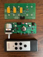
I have a setup below, I also have a 3 channel selector in this one, this setup uses SIRC protocol.
I have a setup below, I also have a 3 channel selector in this one, this setup uses SIRC protocol.
Attachments
Yes, the chip will recieve its commands via the "3-wire-serial-control" from some MCU runnning the application-logic, be it an Arduino, RP2040 or a PIC. The library can only help you to generate the necessary commands.I suppose the chip would be remotely controlled, using a PIC with IR capability, or an Arduino.
If/how/when these commands are transmitted to the attenuator is left to your application. You can use the SPI library for your MCU to realize that. @jpk73 showed an example how to do that on Arduino on this post, but it would look (not exactly but very much) the same for other MCUs.
I have added details of this library to the thread dedicated to: Digital Control of Attenuation – Repository for DIY
Hi @denny9167 ,I have a few C files and some in ASM that I use to program PIC12 chips for controlling a ALPS motorized pot, I havent worked much with digital potentiometers.
I have a setup below, I also have a 3 channel selector in this one, this setup uses SIRC protocol.
I'm still not sure what you are trying to accomplish and how to help to get there. Can you elaborate on that?
I see you have a TSOP4838, which i expect to receive the infrared-signals from the remote-control. It decodes the infrared-waves into a digital signal and feeds it into a PIC12. Your application-logic decodes the transmitted data (according to SIRC specification) and from that results a remote-control-code/"number", which will tell you which button on the remote was pressed.
Based on this information the PIC12 will then increase or decrease the volume by controlling the motor of your ALPS. If you want to replace your ALPS with a digital attenuator, you need to replace the motor-control with the digital commands to tell the attenuator what to do. So instead of letting the motor rotate X steps/seconds/degrees to the desired volume-level, you just send the desired value to the Muses-chip.
This library will generate the digital data you have to send. How to send them was shown by @jpk73. For simplicity of implementation you can use the SPI-library for your PIC12. I think you have to add it via Microchip Code Configurator / MPLabbX IDE to your project. It helps to have a logic-analyser or oscilloscope on hand to check the signals on the three control-lines and test if they look like as described/pictured in the datasheet.
Last edited:
Hi all,
since i realized i had NOT thought about error-handling and still had this uneccesary 0dB-offset for the attenuation-value, i tagged the library as version 0.1 to mark the code as it was at the time of opening of this thread. You can find the old version here. While still a functional piece of software, i do NOT endorse the usage of this version in your projects.
By introducing error-handling on min-/max-boundaries for given parameters one can make sure the requested values are not silently discarded or replaced by min-max-values. This should result in a more robust integration into your software and ease development by aligning with common c-programming-idioms.
As i do not see any further improvements i decided to release version 1.0.0 for general consumption.
Link to source here
Happy coding.
- Home
- Design & Build
- Software Tools
- C-library for MUSES72323