I must admit I am a bit reluctant to post it in this enviroment where one seems to have a verdict allready.....I'll think about it.")
please do let us know what you think of them. Real hands on detail is indeed what this thread needs.
(I'm still curious even if I'm not currently ready to spend my own $$ to find out
)[snip] They were designed to work across a wide range of circuits. It is possible to better the performance by building your own and following the optimization process as the information advises.[snip]-Chris
Chris, are you aware of the Ripple Attenuator Modules (RAM) from Vicor power?
jan didden
Hi Jan,
No, I wasn't aware anyone else had a commercial product like these. Cool, I'll have a look at them. Thank you for posting that!
I have to admit that I pay attention to components, very seldom does a subassy catch my attention. These would not even have been on my radar.
Hi Erik,
I've been very clear that these would work as advertised in all likelihood. No complaints there.
For the average enthusiast, the modules are a great idea. For the person who is simply too busy, they work fine as well. For inclusion into a commercial product being made from scratch - Dunno. You'd have to really sell that to the accounting dept I think. Over the course of a production run, doing these from scratch makes economic sense. If you're only making a few items, buy the completed unit and use it.
To be clear, I only have a problem when something is oversold as a mystery wonder. I'm pretty sure it's been years (decades) since any of us have had recess and stories of magical events. To that end, I'm just trying to keep people honest.
Hi John,
There is something you forgot about John. That is education. People learn by trying things out, by designing and building. Once you stop doing that, you fall behind in technology. You refer to designing and building as a waste of time (for people who don't value their time). I find that comment both sad and arrogant. No matter how much someone learns, there is pride in doing something. If this has no value for you John, that's fine. For me, I have to relearn so much - but I'm doing it. This is not a waste of time for anyone who feels inclined to further themselves. For a self made guy, you have some odd viewpoints there John.
-Chris
No, I wasn't aware anyone else had a commercial product like these. Cool, I'll have a look at them. Thank you for posting that!
I have to admit that I pay attention to components, very seldom does a subassy catch my attention. These would not even have been on my radar.
Hi Erik,
I've been very clear that these would work as advertised in all likelihood. No complaints there.
For the average enthusiast, the modules are a great idea. For the person who is simply too busy, they work fine as well. For inclusion into a commercial product being made from scratch - Dunno. You'd have to really sell that to the accounting dept I think. Over the course of a production run, doing these from scratch makes economic sense. If you're only making a few items, buy the completed unit and use it.
To be clear, I only have a problem when something is oversold as a mystery wonder. I'm pretty sure it's been years (decades) since any of us have had recess and stories of magical events. To that end, I'm just trying to keep people honest.
Hi John,
Do these comments ever end? You had one valid argument for these devices that would suffice. That was ...This is for the 'big boys' to buy, the ones that need a solution, not to keep their hands busy. '-)
Hmmm, pretty detailed for a guy who isn't in on the design details. Carrying on ...It contains IC's but also other added parts. This costs ANYONE time and trouble to source, build and test.
There is a lot of truth in that, and it's a valid way to look at the problem. No complaints from me there. I also support that it should work (just making sure you got that).DIY means that you don't mind wasting many hours of your personal time, but don't try it with a technician. It is cheaper just to buy something ready-built, including modules.
There is something you forgot about John. That is education. People learn by trying things out, by designing and building. Once you stop doing that, you fall behind in technology. You refer to designing and building as a waste of time (for people who don't value their time). I find that comment both sad and arrogant. No matter how much someone learns, there is pride in doing something. If this has no value for you John, that's fine. For me, I have to relearn so much - but I'm doing it. This is not a waste of time for anyone who feels inclined to further themselves. For a self made guy, you have some odd viewpoints there John.
-Chris
Hi Jan,
Here's a link to the Vicor data sheet. To be honest with you, the specs exceed the Bybee model. I'm not sure how much these cost, but they look very straight forward without hyperbole. In fact, this applications noteis far more informative than what we've seen so far. How about that?
All,
If you want a more clear idea of how the Bybee device most probably works, read those links I placed here. Just make sure you heed the Bybee specifications for voltage and current as the Vicor models appear to be rated for higher voltages and currents. I didn't see a model for negative voltages yet. Maybe Vicor has no need of those. So there is something that may recommend the Bybee models.
-Chris
Yes, everyone, please don't listen to me, after all I am a friend of Jack Bybee, and have been for the last 16 years, even though I have actually tried the devices and am going to put them in my best power supplies.
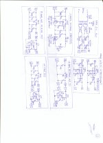
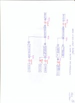
I know the designers, but I don't know the exact circuit, but it is most probably like Fig. 14 in the patent. Sort of a super filtered, actively activated follower. It drops a measured 0.6 V across it as a voltage loss.
Yes, sure, anybody can build one, just get a soldering iron and go to it! ;-)
I know the designers, but I don't know the exact circuit, but it is most probably like Fig. 14 in the patent. Sort of a super filtered, actively activated follower. It drops a measured 0.6 V across it as a voltage loss.
Yes, sure, anybody can build one, just get a soldering iron and go to it! ;-)
Hi John,
We know who you associate with since you constantly remind everyone - that's not been questioned either. I'm not sure what your issue(s) are - is.

Okay, you do understand that you just described a capacitance multiplier there, right? I have to admit I'm a little lost on what an "actively activated follower" is. Is it really, really active? Does the user have to stand there and poke it repeatedly with his or her finger? Help me out on this one - please!
Maybe it's an engineering term, for real engineers.
Just messing with ya there John.
-Chris
Awww, come on John... What do you feel you've said that has been ignored? The devices are going to work, they will probably deliver the stated performance, and for some people it is exactly what they need. So tell me, what do you have a problem with here??Yes, everyone, please don't listen to me, after all I am a friend of Jack Bybee, and have been for the last 16 years, even though I have actually tried the devices and am going to put them in my best power supplies.
We know who you associate with since you constantly remind everyone - that's not been questioned either. I'm not sure what your issue(s) are - is.
Sort of a super filtered, actively activated follower. It drops a measured 0.6 V across it as a voltage loss.
Okay, you do understand that you just described a capacitance multiplier there, right? I have to admit I'm a little lost on what an "actively activated follower" is. Is it really, really active? Does the user have to stand there and poke it repeatedly with his or her finger? Help me out on this one - please!
Maybe it's an engineering term, for real engineers.
Just messing with ya there John.
-Chris
It is more active than a standard follower.
hope it's not a hyperactive follower
(sorry couldn't resist) I know what you are saying, just the wording can be awkward.
Thanks for the honest opinion of the music rails. It's worth quite a lot, even if you are friends with the guys that make them
I may try them out yet...
Hi Jan,
Here's a link to the Vicor data sheet. To be honest with you, the specs exceed the Bybee model. I'm not sure how much these cost, but they look very straight forward without hyperbole. In fact, this applications noteis far more informative than what we've seen so far. How about that?
All,
If you want a more clear idea of how the Bybee device most probably works, read those links I placed here. Just make sure you heed the Bybee specifications for voltage and current as the Vicor models appear to be rated for higher voltages and currents. I didn't see a model for negative voltages yet. Maybe Vicor has no need of those. So there is something that may recommend the Bybee models.
-Chris
It's a relatively straightforward active filter design. They work pretty well; I have one on the supply line of my Hiraga Nemesis which has a very low PSRR.
In fact I believe such a filter unit is overkill on a linear supply but when you use an SMPT for your amp, the filter is really usefull.
Edit: I think I paid about $ 60 for my RAM two years ago. That's single price.
jan didden
Last edited:
The Vicor appears to use a different technique than the Bybee. So the results while similar would not be the same.
Lets be reasonable folks have strong opinions on Mr. Bybee, and acknowledge that influences their view of any product with his name on them.
In the patent application the DC cleanup schematic is a variant I have not seen before. There being a limited number of components and ways to hook them up means it is quite possible someone else may have done similar or the same before. But there is a subtle difference between using the PSSR (Power supply rejection ratio) of an amplifier to get lower noise and ripple than using an amplifier in a feedback mode to correct for errors. The feedback method is subject to load induced instabilities. So there may be something new here!
As to the AC claim I have seen AC stabilizers using boost transformers before, but I do not recall the exact circuit. My recall is that it sort off used a transistor as a variable resistance in the boost transformers primary to maintain a constant output voltage, but with increased distortion.
Originally posted by john curl
Mr. Curl, dare I ask for a less biological (i.e. technical) explanation of this “breathing” ?
Originally posted by anatech
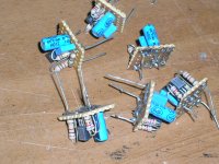
Chris, I have built several one-transistor "Clean-up Shunt"Finesse Voltage Regulator Noise!
as small add-on modules. Three of them are in an FM tuner I built end of 2006.
http://www.diyaudio.com/forums/analogue-source/8089-fm-am-tuner-8.html#post1112711
I could try measure their “clean-up” capabilities if anyone is interested.
Regards
George
Cap multipliers work just fine for many things, BUT they do not fix very low frequency deviations that come from line 'breathing'.
Mr. Curl, dare I ask for a less biological (i.e. technical) explanation of this “breathing” ?
Originally posted by anatech
The mod guys have been on this idea for a few years now. If you look a the FM tuner sites, someone else has an implementation of this on a board they sell. They are installing them in ... tuners. Your friend Dick would be wise to at least feed his local oscillator through a circuit like these.
Chris, I have built several one-transistor "Clean-up Shunt"Finesse Voltage Regulator Noise!
as small add-on modules. Three of them are in an FM tuner I built end of 2006.
http://www.diyaudio.com/forums/analogue-source/8089-fm-am-tuner-8.html#post1112711
I could try measure their “clean-up” capabilities if anyone is interested.
Regards
George
Attachments
Hi George,
Sounds like a cool idea. You will probably need an AC signal amplifier for the noise to be more visible on a 'scope. That's if your supply is reasonable to begin with. I have played with similar circuits, and the one in my reference. They work very well, but it wasn't important to measure the amount. I just noted that is was effective. In situations like these, the amount of effectiveness varies depending on a number of factors. Certainly the way the grounds are run may reduce the effectiveness of any supply cleanup attempt. They are worth including in a design where power supply noise will have a detrimental effect on circuit performance. Serious shielding of the circuit you are supplying would be a natural extension to reduce radiated noise. An MC phono amp comes to mind for the audio hobbyist. In test equipment, the uses are obvious to me and should be to anyone else familiar with the concepts.
Hi Simon,
There are many ways to build an amplifier, and there is always more than one way to achieve similar results. I think that pretty much explains any differences between all other references and Mr. Bybee's product.
So to be clear here. The Bybee branded products surely work as advertised, and similarly as other available products that make similar claims. I don't understand how much more in favour of these products anyone could ask for. It is also very clear that with sufficient knowledge and experience, similar devices can be created by many of our members that will also work well. For any mass market manufacturer, there would be strong motivations to simply design and include these circuits as part of their product. Lower volume products might be better off purchasing a completed unit from one of the vendors.
-Chris
Sounds like a cool idea. You will probably need an AC signal amplifier for the noise to be more visible on a 'scope. That's if your supply is reasonable to begin with. I have played with similar circuits, and the one in my reference. They work very well, but it wasn't important to measure the amount. I just noted that is was effective. In situations like these, the amount of effectiveness varies depending on a number of factors. Certainly the way the grounds are run may reduce the effectiveness of any supply cleanup attempt. They are worth including in a design where power supply noise will have a detrimental effect on circuit performance. Serious shielding of the circuit you are supplying would be a natural extension to reduce radiated noise. An MC phono amp comes to mind for the audio hobbyist. In test equipment, the uses are obvious to me and should be to anyone else familiar with the concepts.
Hi Simon,
Without exact knowledge of how the internals are designed, we really can't say much. I can't see any company giving out the details of their successful commercial products, especially not anything coming from Mr. Bybee. In this case I think it is enough to accept that the results will be similar and that the basic idea is the same.The Vicor appears to use a different technique than the Bybee. So the results while similar would not be the same.
It seems to me that any personal opinions on Mr. Bybees motivations and products haven't had a negative effect here. I am solidly supporting the fact that these things work as advertised. I've even pointed out other products (so has Jan, thank you!) where the performance is similar as support for claims put forth by Mr. Bybee and company. All due respect, but I don't see any prejudice operating here - certainly not from me anyway.Lets be reasonable folks have strong opinions on Mr. Bybee
Again, the devices and other examples have little to do with the circuits they are used in. Improving PSRR is managed in the design of the amplifier or servo, whereas these devices reduce the amount of interference that has to be guarded against. The devices are reducing the noise right at the source, which makes perfect sense. This also agrees with how other similar circuits operate. Notice that my reference runs through a very simple setup (with performance close to what has been claimed) to more elaborate circuits as well. That pretty much covers all the ground that makes up the basic idea.In the patent application the DC cleanup schematic is a variant I have not seen before. There being a limited number of components and ways to hook them up means it is quite possible someone else may have done similar or the same before. But there is a subtle difference between using the PSSR (Power supply rejection ratio) of an amplifier to get lower noise and ripple than using an amplifier in a feedback mode to correct for errors. The feedback method is subject to load induced instabilities. So there may be something new here!
There are many ways to build an amplifier, and there is always more than one way to achieve similar results. I think that pretty much explains any differences between all other references and Mr. Bybee's product.
So to be clear here. The Bybee branded products surely work as advertised, and similarly as other available products that make similar claims. I don't understand how much more in favour of these products anyone could ask for. It is also very clear that with sufficient knowledge and experience, similar devices can be created by many of our members that will also work well. For any mass market manufacturer, there would be strong motivations to simply design and include these circuits as part of their product. Lower volume products might be better off purchasing a completed unit from one of the vendors.
-Chris
Hi John,
One thing I certainly do not buy into is the idea that Mr. Bybee's products are superior to a focused effort for a specific circuit. The commercial implementations have a broad focus so that they will provide a benefit for most situations whereas a design tweaked to address one situation would most probably perform at a higher level.
Just think, and entirely new system tweak that can also allow for "op amp rolling" and even "transistor rolling". This should muddy the waters for quite some time as the mod hacks roll in the green.
There is a definite marketing advantage to using a completed commercial product inside whatever someone else is selling. Ever hear of "wired with Monster cable"? This was popular with amplifiers for a while, and it was even a mod people paid silly money for too! Same idea applies to these devices, except that there will really be an improvement that can be measured (assuming the person measuring has good enough equipment).
I really do think these are a good product for people unable to design and build their own. With the present level of poorly designed power supplies in audio equipment, these may really be the difference between something that sounds really rough and something that you can enjoy listening to. This is something I don't think you would argue with John. There is a real need in the market for these.
-Chris
Okay, as I have mentioned, this is also covered in the link I originally supplied. The devices in Jan's reference are also probably more involved than the more simple implementation in my link. If you read further, they go on to show more complicated filter amplifiers and an explanation as to why higher gain is required. I didn't expect that link to show every permutation as it was intended to give readers the background and idea only. Going further is entirely up to the reader and it's even suggested that people can play with the basics to come to a solution for whatever situation they are dealing with.It is more active than a standard follower.
One thing I certainly do not buy into is the idea that Mr. Bybee's products are superior to a focused effort for a specific circuit. The commercial implementations have a broad focus so that they will provide a benefit for most situations whereas a design tweaked to address one situation would most probably perform at a higher level.
Just think, and entirely new system tweak that can also allow for "op amp rolling" and even "transistor rolling". This should muddy the waters for quite some time as the mod hacks roll in the green.
There is a definite marketing advantage to using a completed commercial product inside whatever someone else is selling. Ever hear of "wired with Monster cable"? This was popular with amplifiers for a while, and it was even a mod people paid silly money for too! Same idea applies to these devices, except that there will really be an improvement that can be measured (assuming the person measuring has good enough equipment).
I really do think these are a good product for people unable to design and build their own. With the present level of poorly designed power supplies in audio equipment, these may really be the difference between something that sounds really rough and something that you can enjoy listening to. This is something I don't think you would argue with John. There is a real need in the market for these.
-Chris
Last edited:
Hi Simon,
Low dropout values normally indicate a shunt regulator. A series low dropout regulator uses the emitter of the pass transistor as the power input. A classic series regulator circuit will have a higher drop out voltage (2 ~ 3 volts for 78xx and 79xx types) because they output the controlled voltage from their emitter. That costs one base emitter drop right off the bat, and probably two since they normally employ a darlington with speedup resistor as a minimal pass circuit. A CCS to feed the pass element bases carries higher performance and also a higher minimum input - output differential voltage penalty. That's why low dropout regulators normally have reduced noise rejection specifications than series pass types do.
Forget about the Vicor product for the moment. I'll agree they were optimized to reduce switch-mode power supply noise - specialized. Not too surprising coming from a company that builds ... switch-mode power supplies!
Looking at the first links I provided, if you read right through, they explain the basic idea and some other ways to implement the design.
Right now we are quibbling about details instead of agreeing on the fact that Bybee's power supply cleanup products here will work as advertised. So just what is it that we have a differing opinion on anyway?
-Chris
and a feed forward noise cancellation function ?.The design works like that patent specifies. It is a SERIES regulator with a low in-out offset.
- Status
- Not open for further replies.
- Home
- General Interest
- Everything Else
- Bybee Music Rails ®