
I was able to source enough Toshiba FETs to build the balanced input version of the BA-3 (with single-ended output), so I decided to go with a dual monoblock version with 32V rails, because why not?
The BOM for the front end and bias boards calls for 10uF caps. I can't get 35V/10uF Silmic caps, but I can get 35V/22uF Silmic or 35V/10uF Panasonic GA-A series. Which would be the best choice?
The BOM for the front end and bias boards calls for 10uF caps. I can't get 35V/10uF Silmic caps, but I can get 35V/22uF Silmic or 35V/10uF Panasonic GA-A series. Which would be the best choice?

I finally got around to finishing the BA-3 with single-ended (BA-1) output boards. I was able to bias the front end with no issues. Now that I've hooked up the output boards, what's the procedure for adjusting them? There's a single pot on the top-mounted bias boards, but I'm not sure what I need to do.
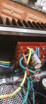
Also, it looks like there are three ground connections per channel going to the power board, not including the chassis ground. These include one each to the front end GND, speaker -, and bias board GND. This differs from the push-pull which does not have the GND pad. Is that correct?
@maltboy1 Yes, the pot is used to zero the DC offset on the output. Bias is automatically set to 0.6A through the source resistor; just make sure you connected the S pad on the bias board to the corresponding pad on the output board if you don’t want things going up in smoke (ask me how I know).
Your power board ground can serve as the star ground for everything. We typically use a CL-60 between chassis ground and the power board ground. Looking at the schematics, the front end and bias board both require a ground wire ran to your PS star ground. Speaker (-) connects to the PS star ground.
I'm using a BA-3 FE and BA-1 output, both running on 32V rails. The PS uses dual 300 VA donuts with a dual monoblock power board. Output is a steady 34V unloaded. The FE bias is currently running at 800mV. The FE biases well with the output disconnected, but the offset re-zeroes itself if I turn either P1 or P2. Is this normal?
The output stage has 0.47R resistors per 6L6's build guide options. When I turned on the amp to set the output offset voltage, I got 14V offset across the speaker terminals! Yikes! The trim pot has little effect on the offset, maybe 200 mA. Any ideas what I managed to muck up?
Figured it out. I had G and D reversed on FE
Attachments
Last edited:
Where are you measuring the FE offset? And what do you mean by “rezeroes itself”?
Unlike the complementary output stage, the SE output stage doesn’t have bias adjustment, and 0.47R source resistor will result in >1.2A. With 32V rails, the dissipation is going to be more than 200W! Or did you stuff the optional r219 resistor to reduce the current as Nelson mentions in the BA-1 article?
Unlike the complementary output stage, the SE output stage doesn’t have bias adjustment, and 0.47R source resistor will result in >1.2A. With 32V rails, the dissipation is going to be more than 200W! Or did you stuff the optional r219 resistor to reduce the current as Nelson mentions in the BA-1 article?
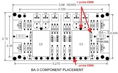
I'm measuring it at R12. I'm measuring bias at R10 and R11. P1 and P2 seem to be somewhat independent. Not like the F5. For example, if I turn P1, the bias on that half changes, and so does the offset, but then the offset reverses direction and goes to 0.
You're right about the heat. I'm going to need to either use r219 or swap the source resistors to 0.68R. The R19 seems like the simpler solution. Does it make a difference which mod is used?
BTW, I hooked it up for a few minutes and it sounds great. Crazy deep soundstage. Superb detail.
You're right about the heat. I'm going to need to either use r219 or swap the source resistors to 0.68R. The R19 seems like the simpler solution. Does it make a difference which mod is used?
BTW, I hooked it up for a few minutes and it sounds great. Crazy deep soundstage. Superb detail.
Make sure you’re not measuring offset across R12 (the drop across R12 will always be close to 0) but from the junction of R12 and the output cap, and ground (ie, one probe between R12 and the output cap, and the other probe at GND; i just hook one probe on the top lead of the output cap and the other to GND).
You are welcome.
I don’t know enough to provide a recommendation about the mod. I can offer these suggestions:
1. Calculate how much you can dissipate for your heatsinks to stay under 55C and make sure the current through the source resistors won’t cause the output stage to dissipate more than that.
2. With the standard 1R source resistor, the ~0.6V drop across it means 0.6A. With 32V rails, that’s 0.6*32*6 = 115W. With 24V rails, that would be lower at 86.4W. (Someone check my math).
3. Higher current is better linearity and better sound (in my opinion). Higher rails means you get higher voltage swing. Both high = higher dissipation.
In my case, I have fairly sensitive speakers and don’t listen that loud, so I went with lower rails (~25V) so I can run 0.6A (1R source resistor). I also tend to be conservative with my builds, and this lets me keep the heatsinks on my 5U Deluxe chassis to around 48C (giving me some headroom for hotter days).
Based on the pic you posted earlier, it looks like you’re using the 4U, and it might be that things would run too hot even with a 1R source resistor.
So, perhaps the r219 mod might be better for you in terms of being able to play with a single resistor to control the current.
So, perhaps the r219 mod might be better for you in terms of being able to play with a single resistor to control the current.
Another thing to consider is that the BA1 output stage is single-ended. Unlike the BA2 (push/pull) version, it cannot drop into class B and deliver current beyond its bias.
Right now, with 0.47 ohm source resistors, I think you have enough current for about 50W into 8 ohms, which is also near the limit of your 32V rails. But if you lower the bias (say with 0.68 ohm source resistors), you probably will only get about 30W (into 8 ohms) before current clipping occurs. This means you won't be able to take full advantage of the higher rails.
The heatsink places a pretty hard thermal limit and you'll have to play with the rail voltages and bias to work within that limit. I believe you mentioned earlier you have 4 ohm speakers. In that case, my first thought is to go with lower rails.
That's a good point. With low ohm speaks you want low rails and lots of bias current, really. But still cool that someone has put together the big SE output stage. Those sound fantastic but don't get very much love around here. My BA-1 was one of my favorites back in the day. I still might revisit it as a winter amp / room heater.
- Home
- Amplifiers
- Pass Labs
- Burning Amp BA-3