Dear all,
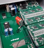
I tried "Reisert Balun" pre and post Power Tx and, of course, it sounds significantly better.
Feel free to add as many fuses as you wish, until your heart's contempt...
Notice the difference in V and I may deserve possibly diverse wiring to comply.
This one is in use on my Dual-mono 8*2 TDA1543 DAC with -EC-'s "balanced charge-transfer supply".
Best wishes,
M.
Attachments
Last edited:
This is a long thread and I might have missed it, but has there been a comparison between the Mosaic UV and the MOS16 and MOS24?
EC - would you care to hint how to mod the UV for using a battery supply?
I am tempted to work out the balanced power solution you mentioned above. Would you suggest one transformer for each item on the chain (Odroid volumio player ->DAC -> tube preamp-> multiple tube/ss amps (tri amped system)) or a large one and how would you scale its power rating vs the total power needed by the equipment? I have a winder locally, any special indications for the isolation transformer?
Would you go with battery supply for the UV or balanced power (particularly if balancing the whole system)?
Last edited:
I got my mojo working!
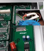
A couple of weeks ago, I installed Black Gates in super E-cap configuration on a 5V circuit (probably the resistor ladder) from the Mosaic DAC.
For the brave who would try these caps on your own circuits, be warned:
Instant darker background with some extra detail, BUT everything else goes wrong for 1 or 2 weeks. Low ceiling and high floor with everything in between sounding "plastic", artificial, though warm, then all kind of variations on the theme, like no lows with crispy highs and vice-versa... Then slowly things begin to improve and soften and relaxing until everything sounds way better than stock. That what is called "authority", with every and all instrument lines perfectly intelligible, with organic textures and timbre. Quite amazing really.
Fortunately, the rescued (used) caps from other experiments take less to "burn-in", like those I am using on my two SD-card players.
These caps are worth every penny.
(old pennies, not present ones)
Best wishes,
M.
A couple of weeks ago, I installed Black Gates in super E-cap configuration on a 5V circuit (probably the resistor ladder
) from the Mosaic DAC. For the brave who would try these caps on your own circuits, be warned:
Instant darker background with some extra detail, BUT everything else goes wrong for 1 or 2 weeks.
Low ceiling and high floor with everything in between sounding "plastic", artificial, though warm, then all kind of variations on the theme, like no lows with crispy highs and vice-versa... Then slowly things begin to improve and soften and relaxing until everything sounds way better than stock. That what is called "authority", with every and all instrument lines perfectly intelligible, with organic textures and timbre. Quite amazing really. Fortunately, the rescued (used) caps from other experiments take less to "burn-in", like those I am using on my two SD-card players.
These caps are worth every penny.
(old pennies, not present ones
) Best wishes,
M.
Attachments
Hi Max,
Nice
Which BG are you talking about please in that experiment ? N, NX, std, etc ?
capacitance value ? Same as John's ?
And have you tried a smd pps cap of a low value... something between 0.1 to 1 uF (with and without the BG) ?
These red ones are non polar, perhaps N (NP?) type, I don't quite remember. Value from these are 220uF/6.3V. For the other functions I have 10uF/50V. Remember these are paralleled in counter-rotating, opposing, foil sense of folding, which allegedly cancels all ill-behavior from caps. I hope I described it well. Google, or better "Brave" (or duckduckgo) for super-E cap, for the monographies that the Black Gate guys produced for this invention.
Cheers,
M.
PS: what is pps?
Last edited:
Hi,
Must be the N if red ! I asked because sometimes a standalone non polar as the Red or the little blue NX just need to be reversed to achieve a different sound as you already know. I meant sometimes it can acheive better results than the sur-E conf... sometimes. that's why I wanted to know if you tried that2 possibilities of the standalone non polar before the Super E (// reverse conf). ?
Remenber, the PPS are the Acrylicsmd caps from Cornell Dublier John was using in the latest tda1541A designs and maybe today yet. Some caps brands make also PPS with higher values 10 uF and more... I found it a good swap for BG. Sometimes I prefer more the PPS with a small capacitance decoupling near the load of digital chips or LDO than a BG... You're right, if we knew we had to buy kilogrames... better ratio than Gold, lol !
Hi,
I meant sometimes it can acheive better results than the sur-E conf... sometimes. that's why I wanted to know if you tried that2 possibilities of the standalone non polar before the Super E (// reverse.
PPS are the Acrylic smd caps from Cornell Dublier.
You're right, if we knew we had to buy kilogrames... better ratio than Gold, lol !
Oh! I did not realize that you were Initiated in the Mysteries.
I confess that I never tried and reverse the BGs...I put them as the Good Lord led me understand.
Different results must be related to circuit idiosyncracies; everything vibrates in this Universe...so I prefer to use the caps as the MFR recommends, in mutually cancelling L configuration.
PPS seem very desirable and affordable. And one can stack many on top, I imagine.
About Gold, just give Him a little more time...
Best wishes of success, peace and prosperity for all,
M.
Hi EC and other folks
.
I need some help:
I have running the dac based on TDA1540 for some time. Simply I have to listen theese "Mother" chips in NOS mode... The dac working good, very good indeed (for My opinion). Power supply is good, classic +5,-5,-18V. No overhating at any part. Jfet 2mA current injection at Iout.
.
But when I unplug the input connector, all of the input pins, values at the input pins are change.
With input pins unlugged, there are +1.594V at the pins.
Also at Riv I have -14mV
.
When pins plugged in and connected I have -0.6mV at the Riv, +0.360V at BCK and DATA, +0.105V at LE.
.
Before DAC inputs I have digital isolation chip ISO7xxx supplied from DAC +5V to +3.3V scale to isolation chip. Also when I turn off the rest from Isolation chip, "upper side", the values are almost the same like pins disconnected?
.
In the datasheet for TDA1540 stated about inputs:
Inputs are TTL compatibile.
Vin low / high = 0.8V / 2V (Max 0V / 7V)
Iin high / low = 50 microA / 200 microA
for all input pins
.
Should I put some pull-up and/or pull-down resistors at the input pins?
.
(I tried published I2S attenuation circuit, with diode array and resistors, BUT I have to remove this because of massive distortion with that circuit)
.
.
I need some help:
I have running the dac based on TDA1540 for some time. Simply I have to listen theese "Mother" chips in NOS mode... The dac working good, very good indeed (for My opinion). Power supply is good, classic +5,-5,-18V. No overhating at any part. Jfet 2mA current injection at Iout.
.
But when I unplug the input connector, all of the input pins, values at the input pins are change.
With input pins unlugged, there are +1.594V at the pins.
Also at Riv I have -14mV
.
When pins plugged in and connected I have -0.6mV at the Riv, +0.360V at BCK and DATA, +0.105V at LE.
.
Before DAC inputs I have digital isolation chip ISO7xxx supplied from DAC +5V to +3.3V scale to isolation chip. Also when I turn off the rest from Isolation chip, "upper side", the values are almost the same like pins disconnected?
.
In the datasheet for TDA1540 stated about inputs:
Inputs are TTL compatibile.
Vin low / high = 0.8V / 2V (Max 0V / 7V)
Iin high / low = 50 microA / 200 microA
for all input pins
.
Should I put some pull-up and/or pull-down resistors at the input pins?
.
(I tried published I2S attenuation circuit, with diode array and resistors, BUT I have to remove this because of massive distortion with that circuit)
.
Last edited:
BTW
EC do You use R-4R concept?
I am asking because I made one "experimental" discrete dac and try 4R-R double connection, made from balanced mode. I think, that somehow the sound is better than classic single ended R-2R, or Balanced R-2R that I tried with the same modules i made. I dont have in circuit "must have" low tolerance resistors I put everyday 1% just to sniff the sound and to check in praxis is it working or not...
Evening gents, quick question; I have one of Ian’s I2S to PCM boards and was going to hook that to a TDA1541A tomorrow and see whether I can do some measurements to confirm the 15 bit resolution issue as reported here. I would however like to compare it to a known working solution with glue logic. Now I’ve seen several posts referring to a glue logic solution by John (ec-designs) but I can’t seem to find that in this monster thread? Any help would be appreciated, thanks!
I don´t seem to remember John making any suggestions to a glue logic solution to Jan´s board, but then again I am getting old. What John did was making his own version of an I2S to PCM solution, that does not have the, presumable, issues Jan's board has. Maybe that is what you are serching for?Evening gents, quick question; I have one of Ian’s I2S to PCM boards and was going to hook that to a TDA1541A tomorrow and see whether I can do some measurements to confirm the 15 bit resolution issue as reported here. I would however like to compare it to a known working solution with glue logic. Now I’ve seen several posts referring to a glue logic solution by John (ec-designs) but I can’t seem to find that in this monster thread? Any help would be appreciated, thanks!
I don´t seem to remember John making any suggestions to a glue logic solution to Jan´s board, but then again I am getting old. What John did was making his own version of an I2S to PCM solution, that does not have the, presumable, issues Jan's board has. Maybe that is what you are serching for?
Yes, perhaps I didn’t word my post properly? It was my understanding that John had posted a I2S to simultaneous (COB) schematic using glue logic at some point, as obviously he’s also running his TDAs in COB mode. I just can’t seem to find the schematic in the +700 pages of this topic?
Evening gents, quick question; I have one of Ian’s I2S to PCM boards and was going to hook that to a TDA1541A tomorrow and see whether I can do some measurements to confirm the 15 bit resolution issue as reported here. I would however like to compare it to a known working solution with glue logic.
There is a solution presented here;
Drive NOS AD1865/62,PCM1704/02/63,TDA1541 from FIFO: Universal I2S-PCM driver board
Maybe this can help?.
Hi JOSI1,
sorry for the late reply,
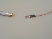
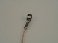
First of all, I developed an electro / optical digital audio hybrid interface that received the name ElectroTos.
The interlink basically consists of a 1 meter coaxial cable driving an ultra high speed LED. This LED shines directly on the Toslink optical receiver. The relatively large distance between wires inside the LED and wires inside the optical receiver provides superb galvanic insulation and almost zero coupling capacitance.
It can run in compatibility mode, this is very interesting for use with existing DACs that have Toslink input. This way the performance of existing DACs that have a Toslink input can be significantly increased.
In native mode the ElectroTos protocol is used, this offers maximum obtainable performance.
So if you want to improve sound quality of existing DACs (including MOS16, MOS24) you can use the new ElectroTos interface plus translator, it will always outperform Toslink by a large margin while preserving advantages of Toslink like perfect galvanic insulation and low bandwidth output.
Ground loop noise + wired LAN will lead to significant sound quality degradation. This is one practical example off how important it is to have -zero- ground loop noise injection. Direct USB, I2S, coax or AES/EBU connection to the DAC cannot prevent ground loop noise injection.
What makes ElectroTos so special?
+ Superb galvanic insulation, zero ground loop noise injection.
+ Limited bandwidth output, massive noise spectrum reduction compared to USB, I2S, coax, and AES/EBU.
+ Extremely low inter-symbol jitter because of twin bandwidth interface (large bandwidth electrical interlink, low bandwidth optical output) and the ElectroTos protocol.
+ No optical reflections.
+ Extra jitter reduction by PLL.
USB
- Poor galvanic insulation, large bandwidth ground loop noise injection.
- Very large bandwidth output, maximum noise injection into the connected DAC.
- High jitter (has to be fixed with an USB receiver that offers asynchronous feedback).
+ No optical reflections.
S/PDIF coax:
- Poor galvanic insulation, large bandwidth ground loop noise injection.
- Very large bandwidth output, maximum noise injection into the connected DAC.
- Poor S/N ratio.
+ Low jitter.
+ No optical reflections.
+ Extra jitter reduction by PLL.
S/PDIF AES/EBU:
- Poor galvanic insulation, large bandwidth ground loop noise injection.
- Very large bandwidth output, maximum noise injection into the connected DAC.
+ Good S/N ratio.
+ Low jitter.
+ No optical reflections.
+ Extra jitter reduction by PLL.
I2S:
- Poor galvanic insulation, large bandwidth ground loop noise injection.
- Very large bandwidth output, maximum noise injection into the connected DAC.
- Poor S/N ratio.
- Medium to high jitter.
- No jitter reduction by PLL.
+ No optical reflections.
Toslink:
+ Superb galvanic insulation, zero ground loop noise injection.
+ Limited bandwidth output, massive noise spectrum reduction compared to USB, I2S, coax, and AES/EBU.
- Very high inter-symbol jitter.
- Optical reflections (fibre optics interlink).
+ Extra jitter reduction by PLL.
In order to get an idea of large bandwidth noise:
I2S, coax and USB (typically 2GHz and up):
################################################################################ (2GHz)
Toslink / ElectroTos
# (25 MHz)
Larger bandwidth noise spectrum will cause much more problems when injected into a DAC. Think of the impact of stray capacitance / inductance and crosstalk. That's why I2S, coax, USB and AES/EBU connection on a DAC will maximise the amount of noise being injected into a DAC and is therefore not a very good idea.
Even worse, when using Toslink, and leaving coax / USB connectors plugged into the DAC, ground loop noise will be injected (bypassing Toslink). There will also be unwanted large bandwidth noise injection into the DAC by the still connected coax / USB sources.
In order to ensure that the Fractal DAC -only- receives one band limited signal (lowest practical noise) and in order to guarantee zero ground loop noise injection, it only has one optical ElectroTos input.
S/PDIF offers the fewest signal changes / second (clock will be recovered from sync codes or preambles), so it will work with lowest practical bandwidth. The single one direction signal is also easy to isolate.
Even if you, by some miracle, find digital couplers that offer zero pF coupling capacitance (input - output), zero noise and zero jitter. These will still inject very large bandwidth noise spectrum (2GHz and up) into the DAC. Once injected into the DAC it's game over, it's like allowing dust to enter a clean room continuously. Once the dust keeps getting into the clean room, there is no way keeping the clean room free of dust no matter what filters you use.
So my different DAC approach forms a noise barrier (air lock) between the source (dusty environment) and the DAC (clean room).
If you want pure involving music reproduction (studio tape quality or better) you use ElectroTos in native mode in combination with the new Fractal / ElectroTos DAC.
This means that the new Fractal DAC will only work with ElectroTos sources. When connected directly to a Toslink source this will result in heavy distortion. So to be absolutely clear, the new Fractal DAC is -not- a Toslink DAC and has totally different properties compared to a Toslink DAC.
The optical receiver in the new Fractal DAC has a standard Toslink socket, but it is -only- intended for use with the ElectroTos interface.
I attached a photograph of an experimental ElectroTos interlink and how it fits into a Toslink optical receiver.
In order to use this new digital audio interface we need a translator. The translator converts USB, S/PDIF coax or Toslink to ElectroTos and reduces jitter. Jumper setting sets either compatibility mode (for use with existing Toslink DACs) or native mode (for use with the Fractal DAC). The translator also contains a special driver circuit for the ElectroTos interlink.
For clarity, when using ElectroTos (compatibility mode) in combination with a Toslink DAC, the DAC will still receive coax signal quality plus superb galvanic insulation. Make sure to pull all other digital interface plugs as failing to do so will bypass ElectroTos, injecting large bandwidth (ground loop) noise. So when comparing sources, always make sure to disconnect all other sources while listening to one specific source!
In order to guarantee maximum performance and minimum interference (crosstalk) we designed two translators:
Asynchronous USB translator based on XMOS 200 series with local low jitter audio clocks. Jumper setting switches between native (for standard Toslink DACs) and ElectroTos (Fractal DAC only).
S/PDIF Toslink / coax translator based on PLL jitter reduction. Jumper setting for Toslink / coax selection and a jumper setting for native and ElectroTos mode. Low jitter coax sources will offer best results. I use an insulation transformer and a differential LVDS receiver for coax in order to get best signal quality and lowest jitter.
The final option is a very clean, guaranteed bit-perfect digital audio source with graphical user interface (PC). This digital audio source has ElectroTos output so it can be directly connected to the DAC. This digital audio source can offer compatibility mode (for existing Toslink DACs) and ElectroTos native mode for the Fractal DAC. One can never be sure what goes on in a PC or streamer, is playback always bit-perfect?
USB digital audio source -> USB interlink -> USB translator (ElectroTos native mode) -> ElectroTos interlink -> Fractal DAC.
USB digital audio source -> USB interlink -> USB translator (compatibility mode) -> ElectroTos interlink -> Toslink DAC
S/PDIF Toslink -> fibre interlink -> S/PDIF translator (ElectroTos native mode) -> ElectroTos interlink -> Fractal DAC.
S/PDIF Toslink -> fibre interlink -> S/PDIF translator (ElectroTos compatibility mode) -> ElectroTos interlink -> Toslink DAC.
S/PDIF coax -> coax interlink -> S/PDIF translator (ElectroTos native mode) -> ElectroTos interlink -> Fractal DAC.
S/PDIF coax -> coax interlink -> S/PDIF translator (ElectroTos compatibility mode) -> ElectroTos interlink -> Toslink DAC.
UPL digital audio source (ElectroTos native mode) -> ElectroTos interlink -> Fractal DAC.
UPL digital audio source (ElectroTos compatibility mode) -> ElectroTos interlink -> Toslink DAC.
No it only accepts ElectroTos and is always used in combination with a translator.
No this causes degrading:
- Large bandwidth (ground loop) noise injection by unused sources.
- Crosstalk
- Jitter.
sorry for the late reply,
First of all, I developed an electro / optical digital audio hybrid interface that received the name ElectroTos.
The interlink basically consists of a 1 meter coaxial cable driving an ultra high speed LED. This LED shines directly on the Toslink optical receiver. The relatively large distance between wires inside the LED and wires inside the optical receiver provides superb galvanic insulation and almost zero coupling capacitance.
It can run in compatibility mode, this is very interesting for use with existing DACs that have Toslink input. This way the performance of existing DACs that have a Toslink input can be significantly increased.
In native mode the ElectroTos protocol is used, this offers maximum obtainable performance.
So if you want to improve sound quality of existing DACs (including MOS16, MOS24) you can use the new ElectroTos interface plus translator, it will always outperform Toslink by a large margin while preserving advantages of Toslink like perfect galvanic insulation and low bandwidth output.
Ground loop noise + wired LAN will lead to significant sound quality degradation. This is one practical example off how important it is to have -zero- ground loop noise injection. Direct USB, I2S, coax or AES/EBU connection to the DAC cannot prevent ground loop noise injection.
What makes ElectroTos so special?
+ Superb galvanic insulation, zero ground loop noise injection.
+ Limited bandwidth output, massive noise spectrum reduction compared to USB, I2S, coax, and AES/EBU.
+ Extremely low inter-symbol jitter because of twin bandwidth interface (large bandwidth electrical interlink, low bandwidth optical output) and the ElectroTos protocol.
+ No optical reflections.
+ Extra jitter reduction by PLL.
USB
- Poor galvanic insulation, large bandwidth ground loop noise injection.
- Very large bandwidth output, maximum noise injection into the connected DAC.
- High jitter (has to be fixed with an USB receiver that offers asynchronous feedback).
+ No optical reflections.
S/PDIF coax:
- Poor galvanic insulation, large bandwidth ground loop noise injection.
- Very large bandwidth output, maximum noise injection into the connected DAC.
- Poor S/N ratio.
+ Low jitter.
+ No optical reflections.
+ Extra jitter reduction by PLL.
S/PDIF AES/EBU:
- Poor galvanic insulation, large bandwidth ground loop noise injection.
- Very large bandwidth output, maximum noise injection into the connected DAC.
+ Good S/N ratio.
+ Low jitter.
+ No optical reflections.
+ Extra jitter reduction by PLL.
I2S:
- Poor galvanic insulation, large bandwidth ground loop noise injection.
- Very large bandwidth output, maximum noise injection into the connected DAC.
- Poor S/N ratio.
- Medium to high jitter.
- No jitter reduction by PLL.
+ No optical reflections.
Toslink:
+ Superb galvanic insulation, zero ground loop noise injection.
+ Limited bandwidth output, massive noise spectrum reduction compared to USB, I2S, coax, and AES/EBU.
- Very high inter-symbol jitter.
- Optical reflections (fibre optics interlink).
+ Extra jitter reduction by PLL.
In order to get an idea of large bandwidth noise:
I2S, coax and USB (typically 2GHz and up):
################################################################################ (2GHz)
Toslink / ElectroTos
# (25 MHz)
Larger bandwidth noise spectrum will cause much more problems when injected into a DAC. Think of the impact of stray capacitance / inductance and crosstalk. That's why I2S, coax, USB and AES/EBU connection on a DAC will maximise the amount of noise being injected into a DAC and is therefore not a very good idea.
Even worse, when using Toslink, and leaving coax / USB connectors plugged into the DAC, ground loop noise will be injected (bypassing Toslink). There will also be unwanted large bandwidth noise injection into the DAC by the still connected coax / USB sources.
In order to ensure that the Fractal DAC -only- receives one band limited signal (lowest practical noise) and in order to guarantee zero ground loop noise injection, it only has one optical ElectroTos input.
S/PDIF offers the fewest signal changes / second (clock will be recovered from sync codes or preambles), so it will work with lowest practical bandwidth. The single one direction signal is also easy to isolate.
Even if you, by some miracle, find digital couplers that offer zero pF coupling capacitance (input - output), zero noise and zero jitter. These will still inject very large bandwidth noise spectrum (2GHz and up) into the DAC. Once injected into the DAC it's game over, it's like allowing dust to enter a clean room continuously. Once the dust keeps getting into the clean room, there is no way keeping the clean room free of dust no matter what filters you use.
So my different DAC approach forms a noise barrier (air lock) between the source (dusty environment) and the DAC (clean room).
If you want pure involving music reproduction (studio tape quality or better) you use ElectroTos in native mode in combination with the new Fractal / ElectroTos DAC.
This means that the new Fractal DAC will only work with ElectroTos sources. When connected directly to a Toslink source this will result in heavy distortion. So to be absolutely clear, the new Fractal DAC is -not- a Toslink DAC and has totally different properties compared to a Toslink DAC.
The optical receiver in the new Fractal DAC has a standard Toslink socket, but it is -only- intended for use with the ElectroTos interface.
I attached a photograph of an experimental ElectroTos interlink and how it fits into a Toslink optical receiver.
In order to use this new digital audio interface we need a translator. The translator converts USB, S/PDIF coax or Toslink to ElectroTos and reduces jitter. Jumper setting sets either compatibility mode (for use with existing Toslink DACs) or native mode (for use with the Fractal DAC). The translator also contains a special driver circuit for the ElectroTos interlink.
For clarity, when using ElectroTos (compatibility mode) in combination with a Toslink DAC, the DAC will still receive coax signal quality plus superb galvanic insulation. Make sure to pull all other digital interface plugs as failing to do so will bypass ElectroTos, injecting large bandwidth (ground loop) noise. So when comparing sources, always make sure to disconnect all other sources while listening to one specific source!
In order to guarantee maximum performance and minimum interference (crosstalk) we designed two translators:
Asynchronous USB translator based on XMOS 200 series with local low jitter audio clocks. Jumper setting switches between native (for standard Toslink DACs) and ElectroTos (Fractal DAC only).
S/PDIF Toslink / coax translator based on PLL jitter reduction. Jumper setting for Toslink / coax selection and a jumper setting for native and ElectroTos mode. Low jitter coax sources will offer best results. I use an insulation transformer and a differential LVDS receiver for coax in order to get best signal quality and lowest jitter.
The final option is a very clean, guaranteed bit-perfect digital audio source with graphical user interface (PC). This digital audio source has ElectroTos output so it can be directly connected to the DAC. This digital audio source can offer compatibility mode (for existing Toslink DACs) and ElectroTos native mode for the Fractal DAC. One can never be sure what goes on in a PC or streamer, is playback always bit-perfect?
Can you provide a sketch showing how these devices are combined/connected.
USB digital audio source -> USB interlink -> USB translator (ElectroTos native mode) -> ElectroTos interlink -> Fractal DAC.
USB digital audio source -> USB interlink -> USB translator (compatibility mode) -> ElectroTos interlink -> Toslink DAC
S/PDIF Toslink -> fibre interlink -> S/PDIF translator (ElectroTos native mode) -> ElectroTos interlink -> Fractal DAC.
S/PDIF Toslink -> fibre interlink -> S/PDIF translator (ElectroTos compatibility mode) -> ElectroTos interlink -> Toslink DAC.
S/PDIF coax -> coax interlink -> S/PDIF translator (ElectroTos native mode) -> ElectroTos interlink -> Fractal DAC.
S/PDIF coax -> coax interlink -> S/PDIF translator (ElectroTos compatibility mode) -> ElectroTos interlink -> Toslink DAC.
UPL digital audio source (ElectroTos native mode) -> ElectroTos interlink -> Fractal DAC.
UPL digital audio source (ElectroTos compatibility mode) -> ElectroTos interlink -> Toslink DAC.
Can a Toslink source be directly connected or only via the New digital audio interface.
No it only accepts ElectroTos and is always used in combination with a translator.
Can I switch between 2 or more inputs via RMC.
No this causes degrading:
- Large bandwidth (ground loop) noise injection by unused sources.
- Crosstalk
- Jitter.
Attachments
- Home
- Source & Line
- Digital Line Level
- Building the ultimate NOS DAC using TDA1541A