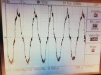
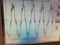
There are certainly differences between the two files. It is easier to see in real time ,. The 24 bit file is more rounded in the top whereas the 16 bit looks more like a clipped sinus.Here is a 90.3dBFS 1kHz 24 bits signal
I can change this into any other level.
Anxious to see what it does with 17bit.
Dropbox - 90.3-24.wav
Hans
P.S., I know about sign magnitude, using 2 Dac's one for positive and the other for negative halve. But I will have a look how John did it.
Pic 1 is 16 bit
Pic 2 is 24 bit
I think I need a -96,31 24bit file to see if bit 17 is resolved
Attachments
Last edited:
By the way I fed the DAC with a -60dB signal an looked at it with the spectrumanalyzer software.
All harmonics are more than 40 dB down from that, so small signal behaviour is fine.
As it is a file that is repeated in Jriver, the 1 Khz dissapears for a moment, and of course the fundamental dissapears too, but the two "harmonics " @ 2 Khz and 3 Khz was still there without changing amplitude (-40 db from the fundamental);-) It must be spuriouses and the actual marmonics are much further down..
I could see on the scope, that the noise increased , when I connected the output from the x100 amp to the input of the soundcard even though the USB port that supplies the Wave IO USB to I2S had an USB isolator before it.
I looked at Johns circuit diagram, and it's clear what he did.By the way I fed the DAC with a -60dB signal an looked at it with the spectrumanalyzer software.
All harmonics are more than 40 dB down from that, so small signal behaviour is fine.
As it is a file that is repeated in Jriver, the 1 Khz dissapears for a moment, and of course the fundamental dissapears too, but the two "harmonics " @ 2 Khz and 3 Khz was still there without changing amplitude (-40 db from the fundamental);-) It must be spuriouses and the actual marmonics are much further down..
I could see on the scope, that the noise increased , when I connected the output from the x100 amp to the input of the soundcard even though the USB port that supplies the Wave IO USB to I2S had an USB isolator before it.
Now we have to do some calculation to understand your image.
The negative Dac goes from 0mA to 4ma while the positive Dac stays at 0mA.
The positive Dac goes from 0mA to 4mA, while the lower one stays at 4mA.
So output current goes from 0mA to 8mA.
When you have a 75Ohm resistor, output voltage is voltage is 600mV +/- 280mV and 1 bit means 560mV/2^16=8.5uV.
(I don't understand the 1k1 resistor, pulling the signal to 600mV in rest, but anyhow.)
On your scope I mean to see 8x 5mV is 40mVpk-pk,
Divided by your 100x amp, this means 40mV /100 = 400uVpk-pk, or almost 50 bits, which seems to correspond with your image, where I really see +/- some 20 levels up and down around zero.
1) With so many levels, signal should almost be impeccable and even better with 17bit.
2) What is not ok is that you get so many bits with this signal.
3) Also the zero crossing looks a bit strange and not sinus like.
Hans
Amen!Hi dear Dreamth,
.
Cheers,
M.
I think the 1K1 is wrong as I said because only the positive DAC needs current sinking to stay @ 0V DC. It needs to be 2K5 with +5V supply. It is easy to see if you seperate the two dacs and measure each output. And this is actually why I dont think the combined two dacs swing 8 mA. In order to stay @ 0V DC the positive DAC needs to have a 2 mA sink and then it can only deliver 2mA as it can only swing 2 mA in one direction from 0V DC. The negative starts with 1111111111111111 and all the current generators are shut off and there is no need for sinking any current. It looks like the combination is kind of asymetric around zero?I looked at Johns circuit diagram, and it's clear what he did.
Now we have to do some calculation to understand your image.
The negative Dac goes from 0mA to 4ma while the positive Dac stays at 0mA.
The positive Dac goes from 0mA to 4mA, while the lower one stays at 4mA.
So output current goes from 0mA to 8mA.
When you have a 75Ohm resistor, output voltage is voltage is 600mV +/- 280mV and 1 bit means 560mV/2^16=8.5uV.
(I don't understand the 1k1 resistor, pulling the signal to 600mV in rest, but anyhow.)
On your scope I mean to see 8x 5mV is 40mVpk-pk,
Divided by your 100x amp, this means 40mV /100 = 400uVpk-pk, or almost 50 bits, which seems to correspond with your image, where I really see +/- some 20 levels up and down around zero.
1) With so many levels, signal should almost be impeccable and even better with 17bit.
2) What is not ok is that you get so many bits with this signal.
3) Also the zero crossing looks a bit strange and not sinus like.
Hans
Try to look at posts #7095 and #7098. This hole thing puzzles me a bit.
Last edited:
The 1k1 is wrong as I said because only the positive DAC needs current sinking to stay @ 0V DC
I don’t understand what you mean, but in fact this resistor is not all too important.
What about the other points that I raised,
do they help you to make any progress ?
Hans
Well I do not know what you are talking about when you are saying you see levels in my scope pictures? I can only see three + zero and - the rest is random noise...I don’t understand what you mean, but in fact this resistor is not all too important.
What about the other points that I raised,
do they help you to make any progress ?
Hans
What is it you do not understand? A TDA1541A in normal operation needs 2 mA input to (or sinking -2mA) in order to stay at 0 V DC with a resistor as I/V stage, otherwise it will clip like crazy.I don’t understand what you mean, but in fact this resistor is not all too important.
What about the other points that I raised,
do they help you to make any progress ?
Hans
But this is when its register is filled with 0000000000000000. That is the situation for the positive DAC so it needs this current (2K5 to +5V PS).
The negative DAC, on the other hand, does not need this as all its currentsources are turned off because it is loaded with 1111111111111111.
I don’t understand what you mean, but in fact this resistor is not all too important.
What about the other points that I raised,
do they help you to make any progress ?
Hans
You are very wrong in assuming that this resistor is not nessesary. It MUST be there when you are using a high value I/V resistor that violates the compliance demands (25 mV) of the TDA1541A. Gross distortion if you leave that out.
I looked at Johns circuit diagram, and it's clear what he did.
Now we have to do some calculation to understand your image.
The negative Dac goes from 0mA to 4ma while the positive Dac stays at 0mA.
The positive Dac goes from 0mA to 4mA, while the lower one stays at 4mA.
So output current goes from 0mA to 8mA.
When you have a 75Ohm resistor, output voltage is voltage is 600mV +/- 280mV and 1 bit means 560mV/2^16=8.5uV.
(I don't understand the 1k1 resistor, pulling the signal to 600mV in rest, but anyhow.)
On your scope I mean to see 8x 5mV is 40mVpk-pk,
Divided by your 100x amp, this means 40mV /100 = 400uVpk-pk, or almost 50 bits, which seems to correspond with your image, where I really see +/- some 20 levels up and down around zero.
1) With so many levels, signal should almost be impeccable and even better with 17bit.
2) What is not ok is that you get so many bits with this signal.
3) Also the zero crossing looks a bit strange and not sinus like.
Hans
In my measurements I did NOT use a 75 Ohm resistor as I/V, but an active opamp virtual gnd connected with 2 KOhm as feedback resistor, so the output is far higher than you use in you calculations +/- 4V with +/- 2mA out as far as I can see.
You are very wrong in assuming that this resistor is not nessesary. It MUST be there when you are using a high value I/V resistor that violates the compliance demands (25 mV) of the TDA1541A. Gross distortion if you leave that out.
Sorry, did I say the resistor is not necessary ?
I said it is not too important in the light of the problems you are facing.
Hans
In my measurements I did NOT use a 75 Ohm resistor as I/V, but an active opamp virtual gnd connected with 2 KOhm as feedback resistor, so the output is far higher than you use in you calculations +/- 4V with +/- 2mA out as far as I can see.
Why do you think you have +/-2mA instead of +/-4mA ?
And what are you using as an oscilloscope, how many bits ?
All the different steps I see are obviously not from your dac but from your scope.
Sorry, did I say the resistor is not necessary ?
I said it is not too important in the light of the problems you are facing.
Hans
I probably misunderstood you when you said you did not understand, why it was there.
And I must also apologize to John, because the value for the bias resistor is correct and the output is indeed 8mA. After fixing the defective GND connection on the RCA plug, I measured the DAC with a 75 Ohm resistor and a trimmer to set DC to 0V.
Now when playing a FS 1 Khz I measure 600 mV over the 75 Ohm I/V resistor and the trimmer, when achieving 0V DC was 1,45 KOhm, but I am using 6,3 V and not 5V for the TDA1541A .
And a quick spectrum analyzer check showed that I could now trim the 2. harmonic lower than the third, as is also the situation when the TDA1541A is in normal mode and with passive I/V.
Still a little high @ -65 dB at the point where 3. harmonic is lowest and a little lower than the 2. (I can trim 2. to -75-80 dB but the 3. is rising then).
Yes you misunderstood me, I didn't understand it's value, not why it was there.I probably misunderstood you when you said you did not understand, why it was there.
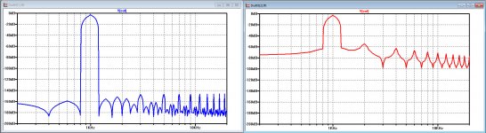
But in search of possible distortion I found something interesting.
I simulated a perfect 1 kHz Sinus composed of two halves.
Playing with the amplitude of one halve only changed the even harmonics, just as expected.
But then I realised that there is a possible time difference between both outputs of 0,2usec max according to the specs.
When shifting the lower halve with this time delay, the spectrum changes completely.
Only this super little delay has dramatic effects.
See below the spectrum at the left for two perfect halves, and at the right when these halves are shifted by 0.2usec.
I didn't pay further attention to simulating the same effect when using 16 or 17 bit resolution.
Hans
Attachments
Yes you misunderstood me, I didn't understand it's value, not why it was there.
But in search of possible distortion I found something interesting.
I simulated a perfect 1 kHz Sinus composed of two halves.
Playing with the amplitude of one halve only changed the even harmonics, just as expected.
But then I realised that there is a possible time difference between both outputs of 0,2usec max according to the specs.
When shifting the lower halve with this time delay, the spectrum changes completely.
Only this super little delay has dramatic effects.
See below the spectrum at the left for two perfect halves, and at the right when these halves are shifted by 0.2usec.
I didn't pay further attention to simulating the same effect when using 16 or 17 bit resolution.
Hans
Very interesting Hans, with the timing between the two halves.
Interesting to see how the noise level also increases.
It is not I think, what happens in the DAC I am dealing with, as the noisefloor is below -110 Db . There is a lot of spuriouses, but the floor is not elevated.
My favorite now is a transformer solution and to me it makes good sense, as it doubles as a pretty effective low pass filter before any active stages.
Concerning PS I would opt for LifePo4 batteries for absolute best performance.
Perhaps galvanic isolation also plays a role in the case of Tx.
We have lots of Li here...we should be making batteries like crazy, but no
Best wishes,
M.
I will do the same sim, but now with 44.1/16.Very interesting Hans, with the timing between the two halves.
Interesting to see how the noise level also increases.
It is not I think, what happens in the DAC I am dealing with, as the noisefloor is below -110 Db . There is a lot of spuriouses, but the floor is not elevated.
Noise floor is dependant on the filter bin width, when you give me the length of the FFT and the sample rate you used, I will use these same figures.
Let's see how this works out.
Hans
Agreed. I also have great results with 6c33c based OTL. Another win was using autoformer volume control replacing any kind of resistor based attenuation. Sounds like I need to try sample transformer I/V.....as I have done a lot to get rid of transformers elsewhere in the chain. (I am using an OTL power amp based on AtmaSpheres Novacron with 4x 6C33)
Max. Would be interesting to hear results of your experiments with Thyratron rectifiers.
- Home
- Source & Line
- Digital Line Level
- Building the ultimate NOS DAC using TDA1541A