Hi all, I am planning to run the I2S out from CS8412 to a PCM63 dac. Has this forum decided on the best way to glue the I2S output to a 2's complement DAC? I've seen 74HC176 used as a shift register, but have seen alternative arrangements as well.
Some q:
1. Can data be sent straight through from cs8412 to PCm63?
2. If so, would you then invert BCK with a 74HC04 while passing LE/WordCK through 2x HC176?
Thanks guys!
I thought this forum was "building-ultimate-nos-dac-using-tda1541a". Maybe we have a forum called "building-ultimate-nos-dac-using-PCM63" ?
")
Why don't you have a look at the TDA1541A specs. I think it's 2's comp device, so you should be able to push clock, latch and data signals straight in, if timing diagrams show they are the same.
Hi Phisci,
More information on this subject can be found here:
http://www.diyaudio.com/forums/digital-source/65948-cs8412-pcm63-non-oversampling.html
1. Can data be sent straight through from cs8412 to PCm63?
More information on this subject can be found here:
http://www.diyaudio.com/forums/digital-source/65948-cs8412-pcm63-non-oversampling.html
Hi, -ecdesigns-
Serg
At early posts you declared that "hearing is believing!", and you have chosen DI. Now you abandoned to DI. What happened to your hearing?Direct interpolation was abandoned
Serg
I attached an oscillogram showing my mains voltage when interference levels are lowest. Most irritating interference is the approx. 2.5 KHz signal riding on the mains.
Next oscillogram shows the 11.2896 Mhz output signal. It's a pure sine wave with very low distortion (fundamental).
Dear EC,
why don't you use a spectrum analyzer ?
How can you visually inspect a sinewave on a scope and claim it has - very low - distortion ?
Same with your 2,5 kHz problem. Why not make a scan 20 Hz to 20 kHz ? It will tell everything.
Not so long ago, - extremely low - jitter proved with 60 MHz Hameg...
Many other things I can not understand, one example, you dropped the DI because hf roll off. But what about the nonos hf roll off ?
I don't think your last post contributes to anything at all...
Dear colleague,
I don't at all try to poke fun at author of the thread – in no event. On the contrary, many EC ideas are close to me. I just try to understand at evolutions of his preferences, at dignities and defects his design.
Sincerely yours,
Serg
Dear colleague,
I don't at all try to poke fun at author of the thread – in no event. On the contrary, many EC ideas are close to me. I just try to understand at evolutions of his preferences, at dignities and defects his design.
Sincerely yours,
Serg
OK.
I think -EC- has explained each and every step he has chosen.
Beside, change in opinion in front of new experiences is sign of a healthy mind. I'm sure we all had an old love that seemed the nec-plus-ultra of beauty and other desirable traits, until a new beloved one de-throned her...
Hi, maxlorenzBeside, change in opinion in front of new experiences is sign of a healthy mind. I'm sure we all had an old love that seemed the nec-plus-ultra of beauty and other desirable traits, until a new beloved one de-throned her...
Thank for so romantic explanation. Probably, you write the poetry.
But speech in post # 4566 went about rumor, about auditory preferences. Gets out that changed the sound ideal?
Serg
SSerg and Berhard have a point: I am also very interested in the differences and similarities between nos roll-off and the effects of the DI dac. Besides, where would humanity be if we could not challenge each other's ideas anymore...?
That being said, i don't think John OWES anyone an explanation. We have come to expect John to be open in sharing his ideas and experiences, and it would be interesting if he could share his experiences in the above aspect also...
That being said, i don't think John OWES anyone an explanation. We have come to expect John to be open in sharing his ideas and experiences, and it would be interesting if he could share his experiences in the above aspect also...
Hi Bernhard,
Too expensive, too low resolution (A/D conversion), and it doesn't capture the information I am interested in.
I didn't mention that I measured sinewave distortion with that scope.
The intermittent 2.5 KHz interference on the mains will stay there with or without measuring it with a spectrum analyser. It is generated outside my house and nobody will ever bother to remove it. It is also very likely that mains interference levels will continue to rise.
So I designed my equipment such way that it becomes highly immune to mains interference.
I mentioned that I check circuit basic operation with a scope. The impact of jitter that the scope can't show is determined by listening tests.
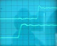
I attached an oscillogram of a novel jitter blocker I am working on.
Upper trace shows the jitter blocker BCK output. Lower trace shows PCM2706 USB receiver jitter (BCK) output before the jitter blocker.
The haze around the transient of the lower signal is clearly visible. So based on this measurement I can at least see that jitter has been reduced and I know the jitter blocker is functioning.
Now listening tests can be performed to further analyse the exact impact of jitter amplitude / spectrum on familiar high quality recordings. This is a fast ane effective method of examining the exact impact of jitter (spectrum) on perceived sound.
why don't you use a spectrum analyzer ?
Too expensive, too low resolution (A/D conversion), and it doesn't capture the information I am interested in.
How can you visually inspect a sinewave on a scope and claim it has - very low - distortion ?
I didn't mention that I measured sinewave distortion with that scope.
Same with your 2,5 kHz problem. Why not make a scan 20 Hz to 20 kHz ? It will tell everything.
The intermittent 2.5 KHz interference on the mains will stay there with or without measuring it with a spectrum analyser. It is generated outside my house and nobody will ever bother to remove it. It is also very likely that mains interference levels will continue to rise.
So I designed my equipment such way that it becomes highly immune to mains interference.
Not so long ago, - extremely low - jitter proved with 60 MHz Hameg…
I mentioned that I check circuit basic operation with a scope. The impact of jitter that the scope can't show is determined by listening tests.
I attached an oscillogram of a novel jitter blocker I am working on.
Upper trace shows the jitter blocker BCK output. Lower trace shows PCM2706 USB receiver jitter (BCK) output before the jitter blocker.
The haze around the transient of the lower signal is clearly visible. So based on this measurement I can at least see that jitter has been reduced and I know the jitter blocker is functioning.
Now listening tests can be performed to further analyse the exact impact of jitter amplitude / spectrum on familiar high quality recordings. This is a fast ane effective method of examining the exact impact of jitter (spectrum) on perceived sound.
Attachments
Hi SSerg,
First of all one gets more critical during development and daily listening tests over long periods of time (years).
I not only rely on my own listening impressions but also on listening impressions of audiophiles.
At the beginning of this thread I was focussing on sample amplitude, smooth signals, low THD and so on. This resulted in the DI system that smoothens the NOS DAC output signal.
Digital audio systems do not output a continuous signal like analogue sources do. They output a sequence of separate packages (samples) where each package holds a specified amount of energy. This sample energy will produce a specified amount of power (watts) in a load.
The exact amount of energy produced by each subsequent sample depends on sample amplitude, sample duration and sample shape. In the ideal case only sample amplitude changes according to sample value while sample duration and sample shape remain exactly the same for all samples.
This has resulted in reverting to one DAC chip, placing main focus on sample duration and sample shape.
At early posts you declared that "hearing is believing!", and you have chosen DI. Now you abandoned to DI. What happened to your hearing?
First of all one gets more critical during development and daily listening tests over long periods of time (years).
I not only rely on my own listening impressions but also on listening impressions of audiophiles.
At the beginning of this thread I was focussing on sample amplitude, smooth signals, low THD and so on. This resulted in the DI system that smoothens the NOS DAC output signal.
Digital audio systems do not output a continuous signal like analogue sources do. They output a sequence of separate packages (samples) where each package holds a specified amount of energy. This sample energy will produce a specified amount of power (watts) in a load.
The exact amount of energy produced by each subsequent sample depends on sample amplitude, sample duration and sample shape. In the ideal case only sample amplitude changes according to sample value while sample duration and sample shape remain exactly the same for all samples.
This has resulted in reverting to one DAC chip, placing main focus on sample duration and sample shape.
Hi studiostevus,
At high frequencies few samples are left for signal reconstruction, at 20 KHz only 2 samples remain for reconstruction.
Unfiltered NOS DAC produces a square wave. Square waves hold highest amount of energy (form factor 1)
Filtered NOS DAC produces a sine wave that holds less energy: 1 / SQRT(2).
DI DAC produces a triangle wave that holds lowest energy: 1 / SQRT(3).
http://en.wikipedia.org/wiki/Form_factor_(electronics)
Suppose an unfiltered NOS DAC with a square wave output of 1Vpp would produce 1 mW in a specified load.
Filtered NOS DAC with a sine wave output of 1Vpp would produce 0.707 mW in that same load.
DI DAC with a triangle wave output of 1Vpp would produce 0.557 mW in that same load.
So unfiltered NOS DAC produces highest energy @ 20 KHz and thus causes lowest trebles roll-off.
Filtered NOS DAC comes next with higher trebles roll-off.
DI DAC causes highest trebles roll-off.
I have been using unfiltered NOS DACs for quite a while, these offer lowest trebles roll-off.
One can apply trebles boost filters for flattening the frequency response. If I am correct trebles boost is also applied in digital brickwall filters. This however conflicts with the statement I made in previous post (wave form of each sample must remain exactly the same).
I am also very interested in the differences and similarities between nos roll-off and the effects of the DI dac.
At high frequencies few samples are left for signal reconstruction, at 20 KHz only 2 samples remain for reconstruction.
Unfiltered NOS DAC produces a square wave. Square waves hold highest amount of energy (form factor 1)
Filtered NOS DAC produces a sine wave that holds less energy: 1 / SQRT(2).
DI DAC produces a triangle wave that holds lowest energy: 1 / SQRT(3).
http://en.wikipedia.org/wiki/Form_factor_(electronics)
Suppose an unfiltered NOS DAC with a square wave output of 1Vpp would produce 1 mW in a specified load.
Filtered NOS DAC with a sine wave output of 1Vpp would produce 0.707 mW in that same load.
DI DAC with a triangle wave output of 1Vpp would produce 0.557 mW in that same load.
So unfiltered NOS DAC produces highest energy @ 20 KHz and thus causes lowest trebles roll-off.
Filtered NOS DAC comes next with higher trebles roll-off.
DI DAC causes highest trebles roll-off.
I have been using unfiltered NOS DACs for quite a while, these offer lowest trebles roll-off.
One can apply trebles boost filters for flattening the frequency response. If I am correct trebles boost is also applied in digital brickwall filters. This however conflicts with the statement I made in previous post (wave form of each sample must remain exactly the same).
I wrote:
You answer:
You made claims about extremely low jitter and later explained verification.
Pardon me if I can not find every one of quotes, the thread is very long.
Here is one:
#1612
Not so long ago, - extremely low - jitter proved with 60 MHz Hameg...
You answer:
I mentioned that I check circuit basic operation with a scope. The impact of jitter that the scope can't show is determined by listening tests.
You made claims about extremely low jitter and later explained verification.
Pardon me if I can not find every one of quotes, the thread is very long.
Here is one:
#1612
-ecdesigns- said:I am using a 60 MHz scope with x10 timebase setting, resulting in 1/600,000,000 = 2nS or 2000ps. Each sub-division (approx. 1mm) represents 2000 / 5 = 400ps. With a low intensity / good focus setting, you can easily subdivide this by 10 (0.1mm), similar to reading a Vernier calliper. This will allow for measuring jitter peak-to peak amplitudes down to 40ps (14ps rms) or better. Then there is the trace brightness, if all clock transients align perfectly, trace brightness appears higher then when they are slightly spread. So a brighter (signal transient) trace also indicates lower jitter amplitude.
Last edited:
I wrote:
You answer:
Are you sure ?
#4548
You post that oscillogram to show us how pure the sine wave is.
How can you visually inspect a sinewave on a scope and claim it has - very low - distortion ?
You answer:
I didn't mention that I measured sinewave distortion with that scope.
Are you sure ?
#4548
Next oscillogram shows the 11.2896 Mhz output signal. It's a pure sine wave with very low distortion (fundamental).
You post that oscillogram to show us how pure the sine wave is.
Last edited:
One can apply trebles boost filters for flattening the frequency response. If I am correct trebles boost is also applied in digital brickwall filters.
Hi EC,
can you post a schematic of some simple circuit that achieves this treble boost for an unfiltered NOS tda1541a Dac ?
I would be very happy if I would be able to test such a filter so I could drop the parametric EQ in my setup that stands right before the power amp just for this purpose; I am using a parametric EQ over a graphic EQ because I can achieve a higher Q slope in compensating high frequency roll-off.
Thanks!
- Home
- Source & Line
- Digital Line Level
- Building the ultimate NOS DAC using TDA1541A