EC Designs,
First off with regard to the Benchmark review. There was allot of stuff that both Benchmark did not know at the time nor did Stereophile.
Like I said... there is no mixer in iTunes. There is in CoreAudio and if you use two applications that output audio it will mix them. This is done at 32bit floating point not 24bit. The Volume control in iTunes has been changed to 32bit a while ago.
Reading some of this older stuff is merely going to confuse you.
It is true that iTunes does not follow sampling rate of the music. That is well documented. But you did not present the information correctly.
Again.......... Assume you are using my Cosecant 24/96 ASYNC dac. It runs at 44.1, 48, 88.2, 96.
When plugged in... CoreAudio is informed of a new Audio device fires up Audio Midi setup and set's it too the default 24/96. If this was a 16 bit dac it would first select 44.1 if available then otherwise the highest rate.
Ok so we start iTunes... it takes a snap shoot of the sample rate 24/96 and will upsample all the songs to that level.
If we leave iTunes and go to Audio Midi setup and set the default rate to 24/44.1 and launch iTunes again it basically send the red book data untouched to CoreAudio which will pad the 8 most significant bits with 0 (same as a cd player) and output the data to the Cosecant.
If we play a higher sample rate song iTunes will downsample and output the data which is not good but not really bad.
~~~~~~
The problem occurs with this... with Audio/Midi set to 24/44.1 and running iTunes we then want to play say an AIFF at 24/88.2. So without leaving iTunes we goto Audio Midi and change the rate to 24/88.2. At that point iTunes will downsample the data to 24/44.1 and then CoreAudio will upsample to 24/88.2.
Before 7.x iTunes did not have an upampler it merly put the data out for CoreAudio to adjust to the output stream.
There are programs in the works that will follow the sample rate. These programs are going to use what is called "HOG" mode. HOG basically indicates to CoreAudio that no other device can use the pipe out to that device. Thereby skipping the mixer.
The mixer in Vista and CoreAudio are similar and are bit accurate.
Thanks
Gordon
I am wondering if there has been some confusion on how the term "mixer" is used.
After all discussions it seems obvious that there is DSP
functionality incorporated into iTunes 7.x, pretty much what this discussion should be all about.
I'd wonder if iTunes can really keep the data at 16/44.1 bit- perfect -
a. after converting them to 32bit float
b. by applying dither on the way back to 16bit , where I am not sure if they are doing it
c. if a PCM270x is used and would be recognised by Core-Audio as a 48kHz device.
It seems that AE is still the savest solution to make sure that "What you get is what you feed". (from a source material perspective)")
Cheers
After all discussions it seems obvious that there is DSP
functionality incorporated into iTunes 7.x, pretty much what this discussion should be all about.
I'd wonder if iTunes can really keep the data at 16/44.1 bit- perfect -
a. after converting them to 32bit float
b. by applying dither on the way back to 16bit , where I am not sure if they are doing it
c. if a PCM270x is used and would be recognised by Core-Audio as a 48kHz device.
It seems that AE is still the savest solution to make sure that "What you get is what you feed". (from a source material perspective)
Cheers
SoundCheck,
All operating systems have mixers. This allows the default audio output device to receive input from several applications.
If you float a 16 bit number (or 24 bit) then convert it back to real again it's the same number.
There is no dither added to a sample by iTunes, CoreAudio or any audio applicaiton that I know of. Though I am sure there maybe a plugin for Foobar or something.
While the nice thing about the PCM270x is that it is simple and yes the MAC or PC will realize it's enumeration for 16 bit 32, 44.1, 48 sample rates. In many ways the part is flawed. The jitter out of the i2s port is really pretty high. This is mainly due to the PLL multiplication and derivation of sample rates. This is the same part used in the first generation of AirportExpress. Too easily understand this try and create 11.2896MHZ from 12MHZ. Basically they multiple 12MHZx8=96MHZ and then do a divide down for 11.2896MHZ (for 44.1). Well let's say it's not spot on and clock multiplication adds jitter out the ying yang.
Actually the AE is not nearly as good as any standalone mac. But it's a simple test if your dac does both SPDIF Toslink and USB.
I have compared and tested them and find the AE a nice little unit, but really out classed by a direct connection to any MAC.
Thanks
Gordon
Hi Gordon,
These links may be interesting
http://www.benchmarkmedia.com/feedback/issues/122007.php
http://extra.benchmarkmedia.com/wiki/index.php/ITunes-QuickTime_for_Mac_-_Setup_Guide
The AE provides bit-perfect playback, jitter should be solved in the DAC, so I don't see the problem here.
Like I said... there is no mixer in iTunes. There is in CoreAudio and if you use two applications that output audio it will mix them. This is done at 32bit floating point not 24bit. The Volume control in iTunes has been changed to 32bit a while ago.
These links may be interesting
http://www.benchmarkmedia.com/feedback/issues/122007.php
http://extra.benchmarkmedia.com/wiki/index.php/ITunes-QuickTime_for_Mac_-_Setup_Guide
While the nice thing about the PCM270x ..... In many ways the part is flawed. The jitter out of the i2s port is really pretty high
The AE provides bit-perfect playback, jitter should be solved in the DAC, so I don't see the problem here.
EC Designs,
Elias is a great guy and he is doing allot for Computer Audio but in general they don't know that much about the Apple system.
I have eight of them here for testing. I also have 5 of those in Bootcamp mode (Xp, Vista, Vista Ultimate, Xp Pro, etc) and have talked to many of the engineers who work in this area at Apple. I also have 5 pc's here of which I developed the motherboard for two of them and wrote bios code for both.
As for jitter... man you can try and get rid of it but it will always happen. If you use like an ARSC it has now been proven that these simply filter the jitter and can never really get rid of it completely. This can be seen in many reviews using ARSC's and reclocking circuits. If it was true that the intrinsic jitter of the dac was constant (as stated by Benchmark and others) then why does it change with various inputs?
Since I completed the ASYNC code for the TAS1020B module I have seen a drop in jitter by 50%. That and I don't really care for the way upamplers sound. As a musician it really kills the low level information that makes music... well music and not musak.
Thanks
Gordon
Hi Gordon,
Have you already checked if you can hear a difference in sound quality between iTunes6 & and iTunes7?
My theory is that in iTunes7, DSP is always active, regardless of settings. This could be based on the assumption that the DSP used in iTunes7 has such high quality, it doesn't need to be disabled like in iTunes6. If I am correct, iTunes6 relies on core audio for DSP, and this clearly reduces sound quality (I verified this by moving the volume slider in iTunes6). So it would be logical not to use core audio (iTunes6) when not required.
In other words, when iTunes6 doesn't need DSP, it wouldn't use it, resulting in bit-perfect playback when all settings are correct.
When using iTunes7, integrated DSP is always enabled /used, on the wrong assumption that there is no audible sound degradation. This could result in failing to achieve bit-perfect playback.
My estimate is that it results in loosing between 1 and 2 bits of dynamic resolution when using 44.1/16 format.
If the connected DAC can only resolve between 14 ... 15 bits (dynamic resolution), this reduced resolution would probably be almost inaudible.
When using external hardware like squeezebox, AE, or Slimserver duet, the data flow is different. Now plain data is sent to the external hardware through a computer network connection (no real-time audio stream). The buffer in the external hardware is filled, and the dedicated electronics in the external hardware generate the real-time audio stream locally, without the intervention of DSP on the computer.
However, it's possible that the computer still messes with the digital audio data before sending it over the computer network when settings are incorrect.
Audio file > DSP > USB / Toslink > ??
Audio file > computer network > processor > USB / Toslink > bit-perfect playback
That's why I now use the AE module, but I just as well could have used a squeezebox or Slimserver duet.
I have eight of them here for testing. I also have 5 of those in Bootcamp mode (Xp, Vista, Vista Ultimate, Xp Pro, etc) and have talked to many of the engineers who work in this area at Apple. I also have 5 pc's here of which I developed the motherboard for two of them and wrote bios code for both.
Have you already checked if you can hear a difference in sound quality between iTunes6 & and iTunes7?
My theory is that in iTunes7, DSP is always active, regardless of settings. This could be based on the assumption that the DSP used in iTunes7 has such high quality, it doesn't need to be disabled like in iTunes6. If I am correct, iTunes6 relies on core audio for DSP, and this clearly reduces sound quality (I verified this by moving the volume slider in iTunes6). So it would be logical not to use core audio (iTunes6) when not required.
In other words, when iTunes6 doesn't need DSP, it wouldn't use it, resulting in bit-perfect playback when all settings are correct.
When using iTunes7, integrated DSP is always enabled /used, on the wrong assumption that there is no audible sound degradation. This could result in failing to achieve bit-perfect playback.
My estimate is that it results in loosing between 1 and 2 bits of dynamic resolution when using 44.1/16 format.
If the connected DAC can only resolve between 14 ... 15 bits (dynamic resolution), this reduced resolution would probably be almost inaudible.
When using external hardware like squeezebox, AE, or Slimserver duet, the data flow is different. Now plain data is sent to the external hardware through a computer network connection (no real-time audio stream). The buffer in the external hardware is filled, and the dedicated electronics in the external hardware generate the real-time audio stream locally, without the intervention of DSP on the computer.
However, it's possible that the computer still messes with the digital audio data before sending it over the computer network when settings are incorrect.
Audio file > DSP > USB / Toslink > ??
Audio file > computer network > processor > USB / Toslink > bit-perfect playback
That's why I now use the AE module, but I just as well could have used a squeezebox or Slimserver duet.
Hi MGH,
The DI4T design is ready, I added a connector for the optional SPDIF cleaner module (part of the twin-VCXO system) on the DI4T mainboard.
I am now selecting / testing the best components for the signal path. I am planning to order some DI4T mainboards soon.
As DI4T performance increased, I had to improve my audio set again. I now use modified bulk metal foil resistors for the entire signal path (passive stepped volume control included), well except for the passive I/V resistors, these are still copper wire types. The passive stepped volume control now holds 28 Vishay VSH1 resistors.
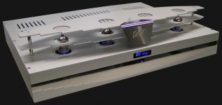
I added a photograph of how the DI4T looks now. The part showing "DI4T" is made from polished stainless steel, it's CNC milled and engraved. Since I was at it, I made a top cover for the DI4T core, with engraved crowns (since I am using 4 x TDA1541A-S1 now).
No, to busy as always, "record" now stands at 18 years without holiday (I didn't have a holiday since I started my company in 1990).
Just wondering if you have the kit finalized.
The DI4T design is ready, I added a connector for the optional SPDIF cleaner module (part of the twin-VCXO system) on the DI4T mainboard.
I am now selecting / testing the best components for the signal path. I am planning to order some DI4T mainboards soon.
As DI4T performance increased, I had to improve my audio set again. I now use modified bulk metal foil resistors for the entire signal path (passive stepped volume control included), well except for the passive I/V resistors, these are still copper wire types. The passive stepped volume control now holds 28 Vishay VSH1 resistors.
I added a photograph of how the DI4T looks now. The part showing "DI4T" is made from polished stainless steel, it's CNC milled and engraved. Since I was at it, I made a top cover for the DI4T core, with engraved crowns (since I am using 4 x TDA1541A-S1 now).
Is EC on vacation?
hmm....
No, to busy as always, "record" now stands at 18 years without holiday (I didn't have a holiday since I started my company in 1990).
Attachments
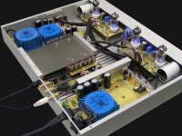
Here is a photograph of the DI4T internal circuitry. I was able to remove another transformer (fewer voltages required because no OP-amps are used). The SPDIF cleaner is still located on a proto-PCB built around a CS8412, the final PCB design will hold a CS8416.
The black trimmers on the tubedif modules are bulk metal foil trimmers, it's quite an improvement over the cermet trimmers. I replaced most of the resistors in the tubedif modules with modified Vishay bulk metal foil resistors, I had to make some small adapter PCBs when multiple resistors had to be used in parallel or series.
I still plan to test Caddock TF020 for the higher resistance values, and Mills wirewound for the higher wattage resistors (twin-cathode follower load resistor).
I probably going to use cryo-treated JJ ECC82 (gold-pin, balanced / matched), and Tungsol ECC803 (gold-pin, balanced / matched). At the moment I am using JJ ECC83S (gold-pin, balanced / matched) for the differential input stages. The tube amplifiers do add complexity, but provide the most transparent sound with highest dynamic resolution.
Both tubediff modules are mounted to the frame using flexible spacers (two hexagonal brass spacers pressed into a clear plastic tube). This reduces microphonics / feedback problems.
The tube sockets are modified ceramic PCB types with gold-plated contacts.
All Molex connectors are also modified to gold-plated contacts (pinheaders & sockets).
Screened wire interlinks are Van Damme studio patch cable (mixed OFC silver-plated & OFC copper wire) with foamed poly-ethylene insulation.
I also used Schottky 1.1KV / 1A Hybrid diodes in the HV tube power supply. These provide a very clean sound, I tested these diodes with a pulse generator, recovery is identical to Schottky diodes. The only high voltage Schottky diodes I could fine were Silicon Carbide versions that can just handle 600 ... 800V, but these are very expensive. So I constructed a Hybrid version, only disadvantage is slightly higher forward voltage drop.
I also increased the capacitance of some electrolytic capacitors, and used versions with better performance.
The white connector supplies 5V to the remote power on / off relay, so all devices connected to the PCU (passive control unit) can be switched-on and off simultaneously using the remote control.
The rear panel is now adapted for the DI4T configuration, the RCA sockets are high-quality gold-plated versions, the sockets are also placed further away from the mains connection when compared with the DI8M design.
There is now one single Toslink input. The Toslink receiver module has enhanced bandwidth and is mounted on the DI4T mainboard.
After testing a lot of different coupling caps, I still prefer the Audyn plus for this specific application. I now use Vishay / Roedersteyn 15nF / 160V precision polypropylene bypass capacitors (the small blue capacitors on the separate PCB). The Audyn plus caps are mounted on flexible lexan holders to reduce problems with mechanical vibrations.
The power consumption of the DI4T has dropped to approx. 30 watts. The TDA1541A heatsink stays quite cool, the DI4T can play all day at high ambient temperatures without problems.
Attachments
Hi Pocoyo,
Yes, it seems like the DI4T finally meets the design objective.
4 x TDA1541A.
None, the DI4T uses tube amplification exclusively. The OP-amp I/V converter was replaced by differential passive I/V conversion.
Look the Ultimate TDA1541A DI4T has finished
Yes, it seems like the DI4T finally meets the design objective.
- how much TDA1541A used ?
4 x TDA1541A.
- how much LM4562 used ?
None, the DI4T uses tube amplification exclusively. The OP-amp I/V converter was replaced by differential passive I/V conversion.
DI4T
Hi ECSDesign
You are so kind and helpfull
- Looks like the total cost to build this DI4T cheaper
enough than DI8 (less parts & less PCB)
- Can you let me know what PCBs used for DI4T
- When this DI4T Launch to market
- Out of your design
We can say "impossible" to find TDA1541S2 now
Is this S2 type make a big difference result with
A type in your DACS Design ?
Thank you ECSDesign
Regards, Jeffry
Re: DI4T
Pocoyo said:Hi ECSDesign
You are so kind and helpfull
- Looks like the total cost to build this DI4T cheaper
enough than DI8 (less parts & less PCB)
- Can you let me know what PCBs used for DI4T
- When this DI4T Launch to market
I'm interested too, bec the DI8 is out of my budget.
Hi Pocoyo,
Yes, the DI4T should be cheaper compared to the DI8M, and it's much easier to build. The following PCBs are used for the DI4T:
1 x DI8PS PCB (existing PCB from DI8, can be used as is, or can be modified to run on one transformer).
1 x TUBEPS PCB (existing PCB from DI8, requires some modifications).
2 x TUBEDIF PCB (existing PCB from DI8, requires some modifications).
4 x DA1541A PCB (existing PCB from DI8, requires some modifications).
1 x DI4TMAIN PCB (new PCB, basically holds most of the DAC circuits).
DI8 PCBs are already available, DI4T mainboard PCB still needs to be manufactured.
4 x TDA1541A:
THD + noise (0dB) = 0.0009%
THD + noise (-60dB) = 0.395%
SN ratio = -118dB
4 x TDA1541A-S2:
THD + noise (0dB) = 0.0007%
THD + noise (-60dB) = 0.223%
SN ratio = -118dB
Differences are marginal, plain TDA1541A will perform excellent.
- Looks like the total cost to build this DI4T cheaper
enough than DI8 (less parts & less PCB)
- Can you let me know what PCBs used for DI4T
- When this DI4T Launch to market
Yes, the DI4T should be cheaper compared to the DI8M, and it's much easier to build. The following PCBs are used for the DI4T:
1 x DI8PS PCB (existing PCB from DI8, can be used as is, or can be modified to run on one transformer).
1 x TUBEPS PCB (existing PCB from DI8, requires some modifications).
2 x TUBEDIF PCB (existing PCB from DI8, requires some modifications).
4 x DA1541A PCB (existing PCB from DI8, requires some modifications).
1 x DI4TMAIN PCB (new PCB, basically holds most of the DAC circuits).
DI8 PCBs are already available, DI4T mainboard PCB still needs to be manufactured.
- Out of your design
We can say "impossible" to find TDA1541S2 now
Is this S2 type make a big difference result with
A type in your DACS Design ?
4 x TDA1541A:
THD + noise (0dB) = 0.0009%
THD + noise (-60dB) = 0.395%
SN ratio = -118dB
4 x TDA1541A-S2:
THD + noise (0dB) = 0.0007%
THD + noise (-60dB) = 0.223%
SN ratio = -118dB
Differences are marginal, plain TDA1541A will perform excellent.
Hi MGH,
It's possible to modify the existing twin-cathode follower on the TUBEDIF modules in order to to create a balanced output. It will involve interrupting some PCB traces and adding some extra components.
However, both DAC groups (inverting and non-inverting groups) output different signals (apart from being in anti-phase). These signals need to be accurately added in order to complete the interpolation process.
When these signals are split, routed along a XLR interlink, and summed in the (pre) amplifier, the slightest imbalance or frequency response / timing differences will lead to increased bit errors.
The TUBEDIF module has a trimmer that allows for correct / accurate summing of these signals.
Balanced outputs also means adding a coupling capacitor (2 coupling capacitors in the signal path). Every (extra) coupling capacitor in the signal path should be avoided whenever possible.
The DI4T signal path is now straight-forward, with very few components in the signal path:
I/V resistor > input amplifier triodes > cathode follower triodes > coupling capacitor > output
best tube performance
Hiii ECSDesign
Who is the best tube performance in your DI4T ?
If will be better if we use tube socket from Teflon with gold-plated
contacts in your system ?
If DI4T use capacitor film for important signal way, please
prepare for bigger place for this, they are big enough
- Teflon
http://www.v-cap.com/tefloncapacitors.html
- Silver in oil
http://www.partsconnexion.com/catalog/CapacitorsFilm.html
Compete between DI4T and DI8
- What is better result from DI4T than DI8
- What is better result from DI8 than DI4T
Looks like the two DAC is from First Breeder
One is German Shiper Dog and others is Golden Retriever
and looks like impossible to have them both
Thanks alot ecsdesign, success 4U 4ever
-ecdesigns- said:I probably going to use cryo-treated JJ ECC82 (gold-pin, balanced / matched), and Tungsol ECC803 (gold-pin, balanced / matched). At the moment I am using JJ ECC83S (gold-pin, balanced / matched) for the differential input stages. The tube amplifiers do add complexity, but provide the most transparent sound with highest dynamic resolution.
The tube sockets are modified ceramic PCB types with gold-plated contacts.
Hiii ECSDesign
Who is the best tube performance in your DI4T ?
If will be better if we use tube socket from Teflon with gold-plated
contacts in your system ?
If DI4T use capacitor film for important signal way, please
prepare for bigger place for this, they are big enough
- Teflon
http://www.v-cap.com/tefloncapacitors.html
- Silver in oil
http://www.partsconnexion.com/catalog/CapacitorsFilm.html
Compete between DI4T and DI8
- What is better result from DI4T than DI8
- What is better result from DI8 than DI4T
Looks like the two DAC is from First Breeder
One is German Shiper Dog and others is Golden Retriever
and looks like impossible to have them both
Thanks alot ecsdesign, success 4U 4ever
Hi Pocoyo,
I currently use JJ ECC83S and JJ ECC82, I am planning to test Tungsol ECC803 as well. I don't use the standard tubes, but factory selected balanced / matched tubes with lowest distortion and lowest microphony with gold-plated pins.
I already use high-quality ceramic tube sockets with gold-plated contacts. This requires the use of tubes with gold-plated pins too. The sound quality doesn't change, but poor contacts are avoided this way.
When you look at the photograph in post #2110 you will notice that I also used professional gold-plated RCA sockets.
All Molex connectors are equipped with partially gold-plated crimp terminals, I also swapped all tin-plated pins from the molex headers with gold-plated versions.
The SPDIF cleaner PCB (located between DI4T mainboard and DI8 power supply) can be removed when real glass-fibre Toslink interlinks are used. These have multiple thin glass fibres. The cheaper interlinks only have a single clear plastic fibre that increases jitter problems and reduces optical output.
Film capacitors act similar as condenser microphones, mechanical vibrations result in small voltage changes. When these capacitors (with solid wires) are mounted directly on the PCB, and the PCB is mounted firmly to the chassis, mechanical vibrations are coupled into the capacitor.
Similar, tube sockets mounted firmly to the chassis will pick-up vibrations that are coupled into the tube metal parts, affecting performance.
In order to prevent this, and enable the use larger film caps in the super flat 1.96" (5cm) high DI4T housing, the film capacitors are mounted on thin flexible Lexan frames, and flexible wires were soldered to the capacitor. The TUBEDIF PCBs are mounted on flexible spacers (clear plastic tube with a hexagonal spacer pressed in on each side). This construction is visible on the photograph in post #2110. The coupling capacitors are the large white ones at each side of the TUBEDIF PCBs. The small blue capacitor, mounted on a small PCB strip between the tubes is the 15nF Vishay / Roederstein MKP1837 precision polypropylene bypass cap.
Note that the DI4T is packed with these kind of details that contribute to refinement of sound quality.
I tested many film capacitors like Auricap, Audyn, Monacor, Obligato, Pulse-x, Siemens, Visaton, WIMA (same capacitance value of 3.3uF and same application), and compared them with a DC-coupling. Each capacitor has specific properties that color the sound, this sometimes sound impressive, but it's not transparent.
Up till now the Audyn plus performs closest to a DC-connection, it doesn't sound "impressive", but the direct comparison with a DC coupling showed it produced the most transparent sound of all caps I tested so far.
The Audyn plus has a special construction, two counter-wound windings, coupled by a "blind" layer. This results in a non-inductive construction. Polypropylene foils always have so called micro-punctures (microscopic holes in the foil). When a single layer is used (like with most capacitors), arcing, and associated noise could occur. Double layers prevent alignment of these micro-punctures, preventing arcs and associated noise.
Audyn plus caps have a very good electrical connection between lead wires and foil. This reduces noise / distortion, and enables handling high peak currents without problems. This makes them suitable for passive, high power speaker crossover filters as well.
The Audyn plus caps are also vacuum treated, and sealed to remove air pockets between the windings. The price is eur 7.69 each, the price/performance ratio is excellent.
I had bad experiences with expensive "boutique" capacitors. All of them have raving reviews, and every manufacturer claims to manufacture the world's best capacitor using special production techniques and materials. They all seem to improve over time like good wine. But when tested in a practical circuit, they often show disappointing results, and some even perform poorer than plain low-cost polypropylene caps.
Most teflon capacitors have problems adapting to DC bias voltages (it takes a long time before the capacitor starts to perform optimally). As soon as the DC voltage is removed, the process starts all over again. This is sometimes solved by leaving the equipment switched-on all the time, but this isn't very practical.
I need a 3.3uF (250V minimum) coupling capacitor for the TUBEDIF module, quick look at the V-CAP TFTF price list indicates $699.99 each, or $979.98 for two!
Silver in oil capacitors sometimes develop DC leakage currents over time, especially when higher DC-bias voltages are applied. They often produce bowling-alley acoustics, this is not transparent. The 3.3uF audio note silver foil in oil cap cost $1936.00 each. This is more expensive than a complete high-performance DAC.
When such expensive coupling caps are actually required, it's time to think about DC-coupled tube amplifiers.
Last year the DI8M (that was later improved significantly), outperformed professional audio equipment like the Lyngdorf digital amplifier (Wolfson 192/24 DAC chip) connected to a North-star transport. It also outperformed the Philips SACD1000, the latest Sony SACD player, and highly modded Sony and Philips CD players. The professional equipment produced a smeared synthetic sound with less detail by comparison. The DI8M had USB-only input at that time.
The DI4T is a massive improvement over the DI8M that's noticed immediately, there is nothing that the DI8M could do better than the DI4T. I have disassembled my DI8M reference DAC and converted it into a DI4T. That should answer your last question.
The DI4T looks similar to the DI8M, but that's where the similarity ends.
Here is a list of the major improvements over the DI8M version:
- Toslink instead of USB, perfect galvanic insulation with zero coupling capacitance. Bit-perfect playback through Apple AE module or CD transport.
- Highly effective jitter blocker (VCXO & loop filter with very low corner frequency of around 0.5 Hz).
- SPDIF receiver runs in slave-clock mode (receives external low jitter timing signals).
- Super clean masterclock & clock buffer power supply (154mH / 10,000uF LC filter). This power supply matches battery power supply performance.
- Non-inverting clock buffers used exclusively (lower jitter values), there are 4 ultra-high speed clock buffers in the DI4T.
- Low jitter masterclock directly drives the 4 TDA1541A chips (no reclocking).
- 4x interpolation instead of 8 x interpolation (less sensitive to jitter, lower I2S interference, better frequency response).
- Highly optimized clock / I2S distribution (minimizing crosstalk), every clock signal path was optimized using damping resistors.
- I2S crosstalk was minimized using special routing techniques and wire links that extend above the PCB surface.
- Improved I2S attenuators with bias voltage (reduces HF interference being injected in TDA1541A substrate).
- New timing-chain, fully synchronous operation, all DAC chips are now latched simultaneously.
- Differential passive I/V conversion (eliminates active I/V converter distortion).
- Tube amplification only (ALL OP-amps removed), results in a more natural transparent high-resolution sound.
- Improved tube amplifiers (all semiconductors removed from the signal path to reduce noise / distortion).
- Improved tube power supply (modified Teddyreg & HV hybrid Schottky diodes), required because gyrators in TUBEDIF module were removed.
- More compact mainboard PCB (shorter connections).
- Local capacitor banks for each TDA1541A chip (12 separate capacitor banks in total).
- Lower output impedance (250 Ohms).
- Lower power consumption, cooler operation.
- Less parts, lower cost, reduced complexity, much easier to build.
Who is the best tube performance in your DI4T ?
If will be better if we use tube socket from Teflon with gold-plated
contacts in your system ?
I currently use JJ ECC83S and JJ ECC82, I am planning to test Tungsol ECC803 as well. I don't use the standard tubes, but factory selected balanced / matched tubes with lowest distortion and lowest microphony with gold-plated pins.
I already use high-quality ceramic tube sockets with gold-plated contacts. This requires the use of tubes with gold-plated pins too. The sound quality doesn't change, but poor contacts are avoided this way.
When you look at the photograph in post #2110 you will notice that I also used professional gold-plated RCA sockets.
All Molex connectors are equipped with partially gold-plated crimp terminals, I also swapped all tin-plated pins from the molex headers with gold-plated versions.
The SPDIF cleaner PCB (located between DI4T mainboard and DI8 power supply) can be removed when real glass-fibre Toslink interlinks are used. These have multiple thin glass fibres. The cheaper interlinks only have a single clear plastic fibre that increases jitter problems and reduces optical output.
If DI4T use capacitor film for important signal way, please
prepare for bigger place for this, they are big enough
Film capacitors act similar as condenser microphones, mechanical vibrations result in small voltage changes. When these capacitors (with solid wires) are mounted directly on the PCB, and the PCB is mounted firmly to the chassis, mechanical vibrations are coupled into the capacitor.
Similar, tube sockets mounted firmly to the chassis will pick-up vibrations that are coupled into the tube metal parts, affecting performance.
In order to prevent this, and enable the use larger film caps in the super flat 1.96" (5cm) high DI4T housing, the film capacitors are mounted on thin flexible Lexan frames, and flexible wires were soldered to the capacitor. The TUBEDIF PCBs are mounted on flexible spacers (clear plastic tube with a hexagonal spacer pressed in on each side). This construction is visible on the photograph in post #2110. The coupling capacitors are the large white ones at each side of the TUBEDIF PCBs. The small blue capacitor, mounted on a small PCB strip between the tubes is the 15nF Vishay / Roederstein MKP1837 precision polypropylene bypass cap.
Note that the DI4T is packed with these kind of details that contribute to refinement of sound quality.
I tested many film capacitors like Auricap, Audyn, Monacor, Obligato, Pulse-x, Siemens, Visaton, WIMA (same capacitance value of 3.3uF and same application), and compared them with a DC-coupling. Each capacitor has specific properties that color the sound, this sometimes sound impressive, but it's not transparent.
Up till now the Audyn plus performs closest to a DC-connection, it doesn't sound "impressive", but the direct comparison with a DC coupling showed it produced the most transparent sound of all caps I tested so far.
The Audyn plus has a special construction, two counter-wound windings, coupled by a "blind" layer. This results in a non-inductive construction. Polypropylene foils always have so called micro-punctures (microscopic holes in the foil). When a single layer is used (like with most capacitors), arcing, and associated noise could occur. Double layers prevent alignment of these micro-punctures, preventing arcs and associated noise.
Audyn plus caps have a very good electrical connection between lead wires and foil. This reduces noise / distortion, and enables handling high peak currents without problems. This makes them suitable for passive, high power speaker crossover filters as well.
The Audyn plus caps are also vacuum treated, and sealed to remove air pockets between the windings. The price is eur 7.69 each, the price/performance ratio is excellent.
I had bad experiences with expensive "boutique" capacitors. All of them have raving reviews, and every manufacturer claims to manufacture the world's best capacitor using special production techniques and materials. They all seem to improve over time like good wine. But when tested in a practical circuit, they often show disappointing results, and some even perform poorer than plain low-cost polypropylene caps.
Most teflon capacitors have problems adapting to DC bias voltages (it takes a long time before the capacitor starts to perform optimally). As soon as the DC voltage is removed, the process starts all over again. This is sometimes solved by leaving the equipment switched-on all the time, but this isn't very practical.
I need a 3.3uF (250V minimum) coupling capacitor for the TUBEDIF module, quick look at the V-CAP TFTF price list indicates $699.99 each, or $979.98 for two!
Silver in oil capacitors sometimes develop DC leakage currents over time, especially when higher DC-bias voltages are applied. They often produce bowling-alley acoustics, this is not transparent. The 3.3uF audio note silver foil in oil cap cost $1936.00 each. This is more expensive than a complete high-performance DAC.
When such expensive coupling caps are actually required, it's time to think about DC-coupled tube amplifiers.
Compete between DI4T and DI8
- What is better result from DI4T than DI8
- What is better result from DI8 than DI4T
Last year the DI8M (that was later improved significantly), outperformed professional audio equipment like the Lyngdorf digital amplifier (Wolfson 192/24 DAC chip) connected to a North-star transport. It also outperformed the Philips SACD1000, the latest Sony SACD player, and highly modded Sony and Philips CD players. The professional equipment produced a smeared synthetic sound with less detail by comparison. The DI8M had USB-only input at that time.
The DI4T is a massive improvement over the DI8M that's noticed immediately, there is nothing that the DI8M could do better than the DI4T. I have disassembled my DI8M reference DAC and converted it into a DI4T. That should answer your last question.
The DI4T looks similar to the DI8M, but that's where the similarity ends.
Here is a list of the major improvements over the DI8M version:
- Toslink instead of USB, perfect galvanic insulation with zero coupling capacitance. Bit-perfect playback through Apple AE module or CD transport.
- Highly effective jitter blocker (VCXO & loop filter with very low corner frequency of around 0.5 Hz).
- SPDIF receiver runs in slave-clock mode (receives external low jitter timing signals).
- Super clean masterclock & clock buffer power supply (154mH / 10,000uF LC filter). This power supply matches battery power supply performance.
- Non-inverting clock buffers used exclusively (lower jitter values), there are 4 ultra-high speed clock buffers in the DI4T.
- Low jitter masterclock directly drives the 4 TDA1541A chips (no reclocking).
- 4x interpolation instead of 8 x interpolation (less sensitive to jitter, lower I2S interference, better frequency response).
- Highly optimized clock / I2S distribution (minimizing crosstalk), every clock signal path was optimized using damping resistors.
- I2S crosstalk was minimized using special routing techniques and wire links that extend above the PCB surface.
- Improved I2S attenuators with bias voltage (reduces HF interference being injected in TDA1541A substrate).
- New timing-chain, fully synchronous operation, all DAC chips are now latched simultaneously.
- Differential passive I/V conversion (eliminates active I/V converter distortion).
- Tube amplification only (ALL OP-amps removed), results in a more natural transparent high-resolution sound.
- Improved tube amplifiers (all semiconductors removed from the signal path to reduce noise / distortion).
- Improved tube power supply (modified Teddyreg & HV hybrid Schottky diodes), required because gyrators in TUBEDIF module were removed.
- More compact mainboard PCB (shorter connections).
- Local capacitor banks for each TDA1541A chip (12 separate capacitor banks in total).
- Lower output impedance (250 Ohms).
- Lower power consumption, cooler operation.
- Less parts, lower cost, reduced complexity, much easier to build.
- Home
- Source & Line
- Digital Line Level
- Building the ultimate NOS DAC using TDA1541A