Hi Everyone,
Somehow other things got in the way of my diy efforts, so I haven't had anything to report for ages. However in the last few days I've got back to the F5 build, and here are some photos.
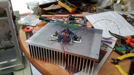
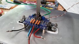
The third shows the hole in the side of the Mac case, where the output transistors and the amp board are fixed on the heatsink. I'm using some caddock MP930 for the source resistors on Q3 and Q4, so these are screwed down on the main heatsink also. The first and second photos show one of the not-quite-finished boards on its heatsink.
I made a couple of errors (probably through doing this while tired...) The first was messing up one of the tapped holed for the standoffs - meaning that on each channel the board is only on three, not four. In this case the board is so small I can't see it matters. (Very irritating, though...) The other was mounting two of the caddock MP930s on the wrong side of Q3 and Q4... (dohhh...) I intended to connect one leg of these directly to the source legs on Q3 and Q4, but this won't work on one side... Oh well. I don;t think it's worth redrilling and tapping two holes...
A question: I'm also using Caddocks for the 10R R1 and R2 on the jfets. I ought to put a little heatsink on them, and was planning on looking through my junkbox to find something. Does anyone have a photo of an appropriate size heatsink? If you look at the photo you can see I intend to put one heatsink for both. I had thought to use Caddocks for the feedback resistors also, but in the interests of getting these things running I think I'll use what I have on hand.
As always, any and all input appreciated.
Even 3 is probably over kill. Mine are hanging off the mosfet's leeds "dead bug" style with no problems. These boards (Peter Daniels F5 boards) are tiny and weigh nothing.
Russellc
What about a sheet of copper, or aluminium, as a cooling spacer between the two resistors?
This is the "default" idea I was going to use if no-one had any other suggestions. About 2 sq. in. or so. Copper if I can find the scraps that are somewhere in the boxes I didn't unpack after my last move, since it is thinner. Alum if not.
I had previously thought of using Caddocks for the feedback resistors also; for the time being I'm not going to, since I forgot to include them the last time I ordered from Mouser, and I'm too cheap to pay postage and packing for four resistors... If I had used them (or if I put them in at a later date) the heatsinking question is a bit more serious - these will get a fair bit hotter. I had planned on using one, larger heatsink that would go through both the jfet resistors and the feedback resistors, since these are in a line. Possibly would need anchoring on the big heatsink.
Even 3 is probably over kill. Mine are hanging off the mosfet's leeds "dead bug" style with no problems. These boards (Peter Daniels F5 boards) are tiny and weigh nothing.
Russellc
Tiny indeed, and you're right that three standoffs is surely more than enough. If I install Caddock feedback resistors one day (as described in my last post) then the heatsink may add enough weight that just mosfet leads might not be adequate, however, and its easier to overdo things now and be prepared than have to rebuild substantially later.
Tiny indeed, and you're right that three standoffs is surely more than enough. If I install Caddock feedback resistors one day (as described in my last post) then the heatsink may add enough weight that just mosfet leads might not be adequate, however, and its easier to overdo things now and be prepared than have to rebuild substantially later.
Naw, I have a set of boards that all the resistors are Caddock....Maybe if one was going to UPS it....
Naw, I have a set of boards that all the resistors are Caddock....Maybe if one was going to UPS it....
Really? What heatsinking, if any, did you use?
The JFET source resistors may need to dissipate more than a watt or so at higher output levels, so a 2W part is the de facto standard here. People get by with less because the ratio of peak to average power for music is much higher than test tones, but I would recommend a small square heatsink on those Caddocks.
The feedback resistors need to be rated to about 6W (though 10 is probably safer), so if you ever decide to use Caddocks in those positions a small heatsink will be definitely required. You can work all of this out using Ohm's law - the two resistors in the feedback chain will see roughly 20V peak, this will give you the peak dissipation figure for the total chain, and the ratio of their dissipation is the ratio of the resistors. The total dissipation is around 6.5W, with the 10R unit seeing about a watt and the other sees the rest of it - if you use the default values.
Strangely in the F5T the resistors need not be so robust, as the voltage across them actually drops quite a bit because of the decreased feedback.
The JFET source resistors may need to dissipate more than a watt or so at higher output levels, so a 2W part is the de facto standard here. People get by with less because the ratio of peak to average power for music is much higher than test tones, but I would recommend a small square heatsink on those Caddocks.
The feedback resistors need to be rated to about 6W (though 10 is probably safer), so if you ever decide to use Caddocks in those positions a small heatsink will be definitely required. You can work all of this out using Ohm's law - the two resistors in the feedback chain will see roughly 20V peak, this will give you the peak dissipation figure for the total chain, and the ratio of their dissipation is the ratio of the resistors. The total dissipation is around 6.5W, with the 10R unit seeing about a watt and the other sees the rest of it - if you use the default values.
Strangely in the F5T the resistors need not be so robust, as the voltage across them actually drops quite a bit because of the decreased feedback.
Hi Sangram,
Thanks for your input. The Ohm's law part isn't the part I find hardest (although I often get it wrong!); my real question is whether people have convenient rules of thumb for what sort of size heatsinking would be adequate to dissipate 6-7 watts, say, in such circumstances. I know you can find data when you're buying a new sink, but when you're going to a junkbox it's harder, especially when you take into account that the ambient temp inside the case will be higher than outside in the room, air circulation may be less than perfect inside the case et cetera. If convenient rules of thumb aren't so easy, maybe pictures of heatsinking in similar situations that was adequate?
Hi
For back-to-back placement like on the PD boards, the 10 ohm MP930 I generally use are fine as they are - they are rated to 2.25C/w without sinks. My guess is that to extend the MP915 to a similar level will require very little metal indeed. A 2x2" piece of 2mm thick material would be sufficient, if you can work out a way to squeeze it in there.
I've used T-shaped pieces with the vertical section stuck into a pair of devices, and strapped on with a cable tie or heat-shrink. You do have mounting holes available, so it's less of an issue.
For Caddocks I prefer to mount them to the sink as far as possible. When retrofitting or fixing mistakes, I've used pretty much what I had on hand and braved it out. Have yet to see one fail, in spite of the dire warnings they are pretty durable unless I did something stupid (like reversed power supplies, that will kill them quick). I've used heatsinks the size of the resistor itself, as well as the SK104 copies we get here. Also small blocks of copper. And a 1" aluminum bar with multiple units bolted to it.
Hi
For back-to-back placement like on the PD boards, the 10 ohm MP930 I generally use are fine as they are - they are rated to 2.25C/w without sinks. My guess is that to extend the MP915 to a similar level will require very little metal indeed. A 2x2" piece of 2mm thick material would be sufficient, if you can work out a way to squeeze it in there.
Hi Sangram,
So in the end I used aluminium; a little smaller than you suggested, but I think it'll be fine. Photos show the completed board on the heatsink. Thanks for the input.
Attachments
An update, and a bug
Hi All,
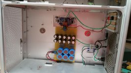
Finished the (first version of the) amplifiers last night. First photo shows the inside of one of them. Unfortunately neither channel is working - no signs of ill health as far as I can see, but no sound, so probably something daft that I forgot...
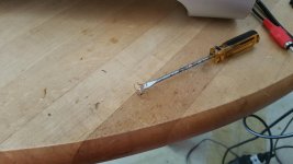
This morning I turned one on to have a look at what is wrong, and a small flash from behind the capacitor board made me turn it off immediately. My first thought was "Oh c**p, I didn't think there was anything wrong with the power supply...", but when I took the board off to take a look behind I found the spider in the second photo (now dead, of course) ...
I'll post an update when I either figure out what's wrong, or I need to cry out for help...
Hi All,
Finished the (first version of the) amplifiers last night. First photo shows the inside of one of them. Unfortunately neither channel is working - no signs of ill health as far as I can see, but no sound, so probably something daft that I forgot...
This morning I turned one on to have a look at what is wrong, and a small flash from behind the capacitor board made me turn it off immediately. My first thought was "Oh c**p, I didn't think there was anything wrong with the power supply...", but when I took the board off to take a look behind I found the spider in the second photo (now dead, of course) ...
I'll post an update when I either figure out what's wrong, or I need to cry out for help...
Attachments

Really? What heatsinking, if any, did you use?
M&M heatsinks. If you go to the "Pics of your Pass amp" there are pics. #165
http://www.diyaudio.com/forums/pass-labs/166784-pictures-your-diy-pass-amplifier-4.html#post2252681
The Caddock boards are on Heatsink USA sinks same as yours I think, 10.08 and 8 inches tall, still in the "Parts in a box stage."
Are you able to bias properly?
You can temporarily disconnect the Caddock in the MOSFET source, this will enable you take various measurements. Your front end would be working properly in such instance.
Be careful about the pinout of the Ztx transistors. If reversed or connected to the wrong polarity, the amplifier will not work. But then you wouldn't have been able to bias properly.
Are you able to bias properly?
Yes; I have biased up to about 530 mV across the source caddocks. The procedure went just the same way as I recall for my last f5 build a couple of years ago, and nothing appears obviously wrong. The heatsinks slowly heat up; slowly enough that I wondered if something was wrong, but I've never got this build up to thermal equilibrium yet, nor is the bias as high as I would expect to have eventually, so the temperature is probably just fine. (And the bolts through the mosfets, and the mosfets themselves, show no signs of being too hot.
You can temporarily disconnect the Caddock in the MOSFET source, this will enable you take various measurements. Your front end would be working properly in such instance.
I can try this easily enough. Any particular measurements in mind? I had thought to switch out the jfets just in case they are the problem. I have them in little sockets, so it is easy enough to do; however once out of circuit they measure just fine for Idss in the little homemade tester I made (years ago) for matching purposes. Can jfets blow in any way that wouldn't show in such a test?
Be careful about the pinout of the Ztx transistors. If reversed or connected to the wrong polarity, the amplifier will not work. But then you wouldn't have been able to bias properly.
I checked this last night, but will do it again. If the ztx were blown then the same would be true, right? The amp just wouldn't work?
As a separate question: can a tube of goop for mica go bad? I don't mean between mica and mosfet and heatsink in use, I mean an old tube of goop from your toolbox. The stuff I used is pretty old, although it looked OK. I don't think this would cause the amp not to work, but it might affect thermal conductivity and heatsink temp, maybe?
I'll keep looking for the fault. It usually turns out to be something daft, and therefore hard to find...
Blown ZTX usually would have no effect on the amp unless it failed short circuit and then you wouldn't be able to bias.
The fact you have bias points to a more basic issue. Maybe a wiring error of some sort?
Can you read the voltage across the 10 ohm Caddock resistors?
May not be easy to read voltage across the 10R Caddocks, but I'll give it a go. There's no need for mica behind them, right?
No, no need for mica.
I can't locate my spare PD PCBs now, but you can also read the voltage between the feedback resistors (the side facing the input devices) and ground, it is the same measurement.
That would be the 'bottom' of either of the CPF resistors and ground, one reading for the ones closer to the +V input, the other from the ones closer to the -V input.
Edit: I would urge you to thoroughly check your SMD handiwork, using an ohmmeter. I hadn't noticed till now that every resistor is a series combination of two parts.
FWIW a Vishay Beyschlag MMA0204 part fits those pads with a bit of stretch, and the MMB0207 is almost a perfect fit. You won't have to bother with the joints in the middle.
I can confirm that P2P does not work well with SMD parts. Been there, not gonna do it again.
Last edited:
I can't locate my spare PD PCBs now, but you can also read the voltage between the feedback resistors (the side facing the input devices) and ground, it is the same measurement.
Voltage across R1 measures as +67mV, across R2 is -62 mV. (These are averages from using two DMMs to make sure not a meter fault.) Is this too low for an amp operating with no input?
(Incidentally, V+ and V- are both 24.2V.)
Edit: I would urge you to thoroughly check your SMD handiwork, using an ohmmeter. I hadn't noticed till now that every resistor is a series combination of two parts.
Actually although some of the SMD parts are in series, others are not, although they are connected with small wires on one side, to reach the pads. (This may be what you meant - if so, my apologies.) I was aware using SMD parts here was a little tricky, so I did them first, and checked with an ohmeter very carefully before doing everything else. Nonetheless, I just checked them again, in circuit, of course:
R13 56.3R, R14 56.4R. (I used 56R resistors, lacking 47R ones)
R15 1.62k R16 1.61k (Seems right when taking circuit into account. Would be tricky to get a more accurate measurement.)
R17 129.6R R18 129.8R (Seems right when taking circuit into account. I can disconnect one leg of the source resistors to check more accurately if necessary.)
R9 100k R10 100k
I couldn't get an accurate reading for R3 and R4, probably due to the thermistor in the circuit. I can take it out and measure again if it's worth the trouble, but seems to me that if R3 and R4 were wrong the circuit wouldn't bias...
FWIW a Vishay Beyschlag MMA0204 part fits those pads with a bit of stretch, and the MMB0207 is almost a perfect fit. You won't have to bother with the joints in the middle.
Worth remembering for next time.
I can confirm that P2P does not work well with SMD parts. Been there, not gonna do it again.
Who knows, maybe I'll be saying the same thing when I get this figured out! It seemed like a good idea at the time, though, and I doubt that it is the basic cause of the problem. (Famous last words!)
Your R1/R2 readings indicate that the JFETs are probably fine.
If R9 and R10 are both 100k, it would seem you have severe attenuation at the input, however there should still be *some* sound, albeit quite faint. R9 should be in 1k - 4k7 range.
You haven't mentioned R3/R4 reading. You should have, from memory, about 700-800 ohms. One will be a bit different from the other, and that's okay. Gate stoppers seem fine and 56R is all right for those parts.
The rest of the readings are okay and/or should not affect sound, as they are related to thermal compensation and current limiting. The amplifier works fine without them. For a while, at least.
Last edited:
Voltage across R1 measures as +67mV, across R2 is -62 mV. (These are averages from using two DMMs to make sure not a meter fault.) Is this too low for an amp operating with no input?
Quoting myself here, I'm trying to figure this out if this is too low or not. A voltage of 67mV means a current of 6.7mA. Looking at the simplified circuit in the F5 manual, Nelson shows a current I1, which is presumably the same as the current that would pass through the 600R R3 shown there; if there is meant to be a voltage of 3.6V, then there is meant to be a current of 3.6/600 = 6mV through the jfet. (Presumably the jfet's Idss controls this, right?)
I measure a voltage of 50mV or so through the R5//R7 pair, so basically no current at all. Is this right for feedback resistors when there is no signal?
- Status
- This old topic is closed. If you want to reopen this topic, contact a moderator using the "Report Post" button.
- Home
- Amplifiers
- Pass Labs
- Building F5 monoblocks in Apple G5 cases