Here's a brief update on progress, for anyone who may be following. I've been drilling and filing, and getting the transformers and related stuff up and running.
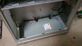
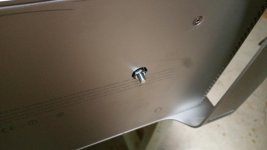
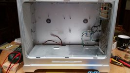
The first photo shows the transformer, rectifier bridges, the thermistors on the primaries, and the Y2 cap across the mains. Green wire is safety earth. (Ignore the other green wire that goes nowhere. I intended to put the third thermistor from signal ground to earth on the same strip, but changed my mind.) Second photo shows the steel PSU box closed up in the bottom of the G5 case. One slight limitation is that because the bottom of the PSU steel case is right up against the bottom of the main chassis, anything screwed to the bottom needs a relief hole through the main chassis. The third photo shows this for the transformer; I've avoided this for the bridges and other stuff, which can be bolted through the rear. However if any serious use was to be made of the extra space in the PSU box then a different solution would be needed.
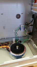
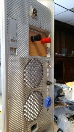
The fourth photo shows things with the top of the PSU removed. One thing I might try and do differently if I ever did this again would be the mains power inlet. The one on the PSU box is quite nice, and could be repurposed. However I couldn't see a convenient way to mount a switch and fuse, so I opted to install a Neutrik Powercon socket, and to use a screw-down connector strip to connect things together, and to leave the PSU box as something that can be removed easily. In retrospect, maybe I could have found a better solution, but I think this one will work OK. The fifth photo shows the rear from outside; you can see the ugly hole where the power inlet was. (The horrid MDF is temporary, and will be replaced with aluminium at some point.)
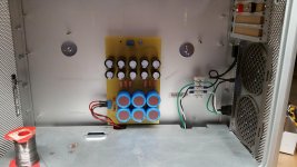
Finally, sixth photo shows the PSU unit installed and wired up. Notice that there is a steel shelf that installs on top of the PSU box; although I don't expect to make any immediate use of this, if I decide to change to a CLC filter it might be natural to mount the inductors to this. (If the space inside the PSU box is insufficient.) I fancy the idea, but I think I'll get everything running with the standard CRC first.
As always, any comments very welcome, including any that might not be relevant to my build, but might be if anyone else wants to try this.
Best
Nigel
The first photo shows the transformer, rectifier bridges, the thermistors on the primaries, and the Y2 cap across the mains. Green wire is safety earth. (Ignore the other green wire that goes nowhere. I intended to put the third thermistor from signal ground to earth on the same strip, but changed my mind.) Second photo shows the steel PSU box closed up in the bottom of the G5 case. One slight limitation is that because the bottom of the PSU steel case is right up against the bottom of the main chassis, anything screwed to the bottom needs a relief hole through the main chassis. The third photo shows this for the transformer; I've avoided this for the bridges and other stuff, which can be bolted through the rear. However if any serious use was to be made of the extra space in the PSU box then a different solution would be needed.
The fourth photo shows things with the top of the PSU removed. One thing I might try and do differently if I ever did this again would be the mains power inlet. The one on the PSU box is quite nice, and could be repurposed. However I couldn't see a convenient way to mount a switch and fuse, so I opted to install a Neutrik Powercon socket, and to use a screw-down connector strip to connect things together, and to leave the PSU box as something that can be removed easily. In retrospect, maybe I could have found a better solution, but I think this one will work OK. The fifth photo shows the rear from outside; you can see the ugly hole where the power inlet was. (The horrid MDF is temporary, and will be replaced with aluminium at some point.)
Finally, sixth photo shows the PSU unit installed and wired up. Notice that there is a steel shelf that installs on top of the PSU box; although I don't expect to make any immediate use of this, if I decide to change to a CLC filter it might be natural to mount the inductors to this. (If the space inside the PSU box is insufficient.) I fancy the idea, but I think I'll get everything running with the standard CRC first.
As always, any comments very welcome, including any that might not be relevant to my build, but might be if anyone else wants to try this.
Best
Nigel
Attachments

is that the pic of the 1uF you refer to in the text "The Y2 capacitor across the mains is 1uF, which seems high,"The power socket on the power supply of the G5 has a heat-shrinked filter arrangement on it. I cut one open (since I thought the wires were a little too thin) so here's what's inside. The Y2 capacitor across the mains is 1uF, which seems high, although there are two other components which look like caps from live and neutral to earth, so maybe that affects things in some way. The ferrite is handy, and I expect to use it, with a 0.0033uF cap as in the original design and slightly heavier wires. Does anyone know for sure what the blue components are? The only marks I can read say CS102M so maybe they're Y class caps of some kind? Any point in keeping them?
Of course, a G5 computer pulls plenty of current, and this arrangement must be safe enough, so anyone who wants to can presumably use it without pulling the heatshrink off...
That is indeed very high for a Y2 capacitor. But I see X2 printed on there!
Is it too late to make the pair mirror image of each other (like bookends)?
I agree this would look better, but it isn't so easy. The left-hand side of the case that the heatsinks are mounted on is part of a large 1/8" aluminium sheet that is bent round to make the bottom and top of the Apple case as well, and is very rigid. The other side is a removable panel (with a clever locking system). So to have "bookend" style mirror images you would have to mount one of the heatsinks on this removable panel, which would probably need screwing to the case to reinforce the locking mechanism, and longer wires from the board, and so on. It's definitely possible, but it would be much more complicated, and much less convenient for opening the case up and tweaking things later on, so I decided to keep things simple.
Incidentally, if anyone wants to build a dual mono machine in a single case then you would presumably mount the second heatsink by some means like this. There is space in the PSU box for a second transformer, and loads of space for a second board of capacitors. A stereo build with a single power supply would need a much bigger transformer, which would (probably) be too tall to fit into the PSU box. The other style of Apple case (the "Pro", I think) might be better if you need to put a bigger (that is, taller) transformer in.
Best
Nigel
is that the pic of the 1uF you refer to in the text "The Y2 capacitor across the mains is 1uF, which seems high,"
That is indeed very high for a Y2 capacitor. But I see X2 printed on there!
My bad. That is a typo, and should read X2, indeed. (How did I miss that?)
The question stands, though. Isn't it high for an X2 cap across the mains line? And what are the little blue components (with unreadable markings)? Y2 caps? One presumes Apple knows what they are doing, but perhaps the demands of a computer are different, somehow? It doesn't really matter for my build, since I've replaced it all with a 0.0033 cap, as per the F5 manual, but if anyone else does this it would be helpful to know what's under the heatshrink in the PSU. If it could just be left as an EMI filter (or whatever it is) then someone might want to do so.
Best
Nigel
Hi Andrew,
That makes sense.
Somewhere on this site I was reading that large X2 caps might generate a lot of heat... I'll have to search and read up on it sometime; I'd like to understand this better.
The computer's AC to DC smps needs filtering to help attenuate the emi it sends back down the line.
That makes sense.
Somewhere on this site I was reading that large X2 caps might generate a lot of heat... I'll have to search and read up on it sometime; I'd like to understand this better.
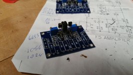
Here's another update. I've installed the PSU boards, as in the first photo. These are point-to-point, and use some old caps I had hanging around together with some new ones. At the moment these are C-R-C, each rail being 30,000uF - 1R - 23,500uF. This should be plenty for each monoblock, although I wonder about maybe switching the order to 23,500 - 1R - 30,000... I'll probably leave that for the time being, since I may experiment with C-L-C later.
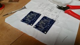
I've also started stuffing the main amp PCBs. These are a pair I bought online from Peter Daniels some years ago, that have been sitting around waiting for me to get busy. The schematic is the original F5, not the revised one.
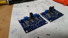
One slight issue with these boards is that they are very small, and the through-hole resistors I have (mostly Dale RN55 and RN60) won't fit easily on it without mounting them vertically. Since this is awkward (not to mention ugly) I've decided to use some SMD resistors I have lying around. These are mostly thin-film resistors with very strict tolerances and good temperature stability, so I went ahead and put them in for everything except R19 and 20 (I had nice small through-hole ones), R5 - R8 and the source resistors R11 and R12 (all of which are much higher power rating) and the gate stoppers R13 and R14 on the mosfets. I don't have any 47R SMDs, although I do have some 56R, but having just two vertically mounted resistors doesn't seem like a big deal. The SMD resistors probably have tighter tolerances - anyone have an opinion on how much of a difference changing 47R to 56R would have? Extrapolating from remarks in the big F5 thread, it seems not to matter much, but what difference would it make? Am I right in thinking that the gate stopper is there to help stop the amp oscillating, and unless it does, then the actual value doesn't matter much?
Getting the SMD resistors on there was tricky, but fun. Because 0805 are too small to reach between the holes, I had to solder in little wires to reach one end. In the case of the 2.2k resistors I had to put a 1k and a 1.2k on in series, which I tried just to see if I could do it, and was actually easier than I expected.
I've also started stuffing the main amp PCBs. These are a pair I bought online from Peter Daniels some years ago, that have been sitting around waiting for me to get busy. The schematic is the original F5, not the revised one.
One slight issue with these boards is that they are very small, and the through-hole resistors I have (mostly Dale RN55 and RN60) won't fit easily on it without mounting them vertically. Since this is awkward (not to mention ugly) I've decided to use some SMD resistors I have lying around. These are mostly thin-film resistors with very strict tolerances and good temperature stability, so I went ahead and put them in for everything except R19 and 20 (I had nice small through-hole ones), R5 - R8 and the source resistors R11 and R12 (all of which are much higher power rating) and the gate stoppers R13 and R14 on the mosfets. I don't have any 47R SMDs, although I do have some 56R, but having just two vertically mounted resistors doesn't seem like a big deal. The SMD resistors probably have tighter tolerances - anyone have an opinion on how much of a difference changing 47R to 56R would have? Extrapolating from remarks in the big F5 thread, it seems not to matter much, but what difference would it make? Am I right in thinking that the gate stopper is there to help stop the amp oscillating, and unless it does, then the actual value doesn't matter much?
Getting the SMD resistors on there was tricky, but fun. Because 0805 are too small to reach between the holes, I had to solder in little wires to reach one end. In the case of the 2.2k resistors I had to put a 1k and a 1.2k on in series, which I tried just to see if I could do it, and was actually easier than I expected.
Attachments
I like your work.
Thanks. Whether I like it or not will depend on how it sounds...
")
I've noticed that although the SMD resistors I put on (photo a couple of posts above) are surely going to be fine for the most part, for R1 and R2 little 0805 1/8W resistors aren't going to be able to handle the heat. I was a little unsure about this, but after checking in the big F5 thread this, where there are several posts talking about it, it is clear they have to be changed. Fortunately I have some MP915 Caddocks I can "borrow" from another project that I bought parts for and haven't started yet, so I'll put those on.
Does anyone spot any other resistors that might be problematic as SMD? The feedback resistors will be four Dale 3W 100R, and the source resistors R11 and 12 on the mosfets will be 0R5 MP30 Caddocks, but otherwise 0805 parts look good to me except possibly the gate stoppers R13 and 14. If I understand correctly, these should also be OK at 1/8W in normal operation - I'm looking through the big thread for info now. Anyone reading this know the answer? It's an awful big thread to find things in...
Does anyone spot any other resistors that might be problematic as SMD? The feedback resistors will be four Dale 3W 100R, and the source resistors R11 and 12 on the mosfets will be 0R5 MP30 Caddocks, but otherwise 0805 parts look good to me except possibly the gate stoppers R13 and 14. If I understand correctly, these should also be OK at 1/8W in normal operation - I'm looking through the big thread for info now. Anyone reading this know the answer? It's an awful big thread to find things in...
gate stoppers - small ones are OK
Thanks, ZM!
Just saw this thread - AWESOME!!!
Looking forward to seeing more photos.
As requested, here are a couple more pics...
Boards are mostly complete. Still need the feedback resistors, but the source resistors will be on the heatsinks with the mosfets. I've replaced the SMD R1 and R2 as discussed above, using a couple of Caddock MP915. These aren't soldered in yet, since I am deciding how high I want to put them for air circulation. Since they are going to be tight together I am planning on putting some form of heatsink between them, to work for both. According to discussion in the big thread this shouldn't be necessary, strictly speaking, since they should be good for 1W in free air, but as tight together they aren't so "free", and it can't hurt to put a little something in there.
One side effect of putting the Caddocks in is that it will be hard to link the two jfets thermally. I was planning on making some kind of little heatsink to do this, a little like the ones Patrick did the group buy for a few years ago, but with the Caddocks in the way this will require some thinking...
For the time being I've used the little sockets for the small signal stuff. These can be removed if/when I'm ready, but they'll make switching things in and out much easier if I experiment (or let the smoke out...). I'm making this using IRPF240 for the N-channel, and the Fairchild equivalent for the P-channel since they are what I had in my old build and I can reuse them, but I may try the Toshiba outputs later on, and in this case the matching business (and EUVL's degeneration resistor trick) would be fun to try.
Attachments
An update after a long break...
Hi Everyone,
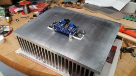
Somehow other things got in the way of my diy efforts, so I haven't had anything to report for ages. However in the last few days I've got back to the F5 build, and here are some photos.
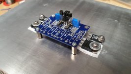
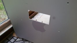
The third shows the hole in the side of the Mac case, where the output transistors and the amp board are fixed on the heatsink. I'm using some caddock MP930 for the source resistors on Q3 and Q4, so these are screwed down on the main heatsink also. The first and second photos show one of the not-quite-finished boards on its heatsink.
I made a couple of errors (probably through doing this while tired...) The first was messing up one of the tapped holed for the standoffs - meaning that on each channel the board is only on three, not four. In this case the board is so small I can't see it matters. (Very irritating, though...) The other was mounting two of the caddock MP930s on the wrong side of Q3 and Q4... (dohhh...) I intended to connect one leg of these directly to the source legs on Q3 and Q4, but this won't work on one side... Oh well. I don;t think it's worth redrilling and tapping two holes...
A question: I'm also using Caddocks for the 10R R1 and R2 on the jfets. I ought to put a little heatsink on them, and was planning on looking through my junkbox to find something. Does anyone have a photo of an appropriate size heatsink? If you look at the photo you can see I intend to put one heatsink for both. I had thought to use Caddocks for the feedback resistors also, but in the interests of getting these things running I think I'll use what I have on hand.
As always, any and all input appreciated.
Hi Everyone,
Somehow other things got in the way of my diy efforts, so I haven't had anything to report for ages. However in the last few days I've got back to the F5 build, and here are some photos.
The third shows the hole in the side of the Mac case, where the output transistors and the amp board are fixed on the heatsink. I'm using some caddock MP930 for the source resistors on Q3 and Q4, so these are screwed down on the main heatsink also. The first and second photos show one of the not-quite-finished boards on its heatsink.
I made a couple of errors (probably through doing this while tired...) The first was messing up one of the tapped holed for the standoffs - meaning that on each channel the board is only on three, not four. In this case the board is so small I can't see it matters. (Very irritating, though...) The other was mounting two of the caddock MP930s on the wrong side of Q3 and Q4... (dohhh...) I intended to connect one leg of these directly to the source legs on Q3 and Q4, but this won't work on one side... Oh well. I don;t think it's worth redrilling and tapping two holes...
A question: I'm also using Caddocks for the 10R R1 and R2 on the jfets. I ought to put a little heatsink on them, and was planning on looking through my junkbox to find something. Does anyone have a photo of an appropriate size heatsink? If you look at the photo you can see I intend to put one heatsink for both. I had thought to use Caddocks for the feedback resistors also, but in the interests of getting these things running I think I'll use what I have on hand.
As always, any and all input appreciated.
Attachments
If those resistors are 0.5W or greater you don't need heatsink.
Well, the MP915 is rated for 1.25 watts in free air (according to the datasheet). However, this pair are mounted almost back-to-back, so neither is really in free air, if you see what I mean. I thought that I'd screw some kind of small heatsink between them, as a little insurance. I only used the caddocks because I had them in my parts box for some reason I can't remember, but it makes sense to me to put some heatsink there, since that's how they're designed to work, and I was curious to see what other people have used.
- Status
- This old topic is closed. If you want to reopen this topic, contact a moderator using the "Report Post" button.
- Home
- Amplifiers
- Pass Labs
- Building F5 monoblocks in Apple G5 cases