Sure, that's going to be vast overkill as they could manage 0.8 ohm
Something between 18 and 27V -not critical at all-
ok thanks for all and sorry for my stupid questions.
so, I think I'll use this transistors MJL21194 and this transformer 225VA 30v+30v
do you think it's enough?
thanks 1000 for patience.
A.
A 30V transformer will result in ~40V DC rails, not 25V.
The possible power on 8 ohm will be ~80W/ch, which is manageable.
You could use 33 to 43V zeners
yes! thanks
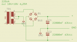
It is perfectly OK, you can feed both channels with it (or even more, if you fancy it)
thanks a lot....
Entropy, as in days, months, years, has been eroding the links. You know that car you bought years ago that you still think is pretty? Just like that, eventually. Although a good amp, the "new" has worn off.
Yes, it has come time for Circlophone2, the almost switching much more efficient version; but, it is too soon for that. I'm just *predicting* that is *possibly* coming and not a bit sooner than the evident need of it. But, that one will run cool. The parts count might go up by a third though.
Hi!
What about that new design?
Any news?
Would you suggest to start from scratch the original one (althought no links are working now...) or better to wait for the new one?
Thank's a lot for a beautiful thread.
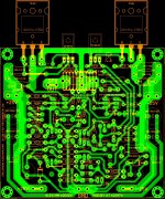
Can anybody help me to convert this pcb layout from sprint to gerber?
thanks
Burnt R10- 2nd time
Hello Folks !
By mistake switched on my set up with full volume, one mid range channel went up in smoke . later inspection revealed burnt R10 (15 ohms resistor ) and completely charred 10 ohms 3W resistor connected in series to output.
No visible damage whatsoever on remaining 4 circlophones - they are running just like before.
This is happening 2 nd time . what could be the reason for this
Last time also it was single channel in mid range when CD player which was connected, started with full volume by mistake.
My setup :
Source: Raspberry pi with Alloo boss DAC running volumio OR Bluetooth receiver
linkwitz riley 3 way active crossover (published in silicon chip magazine)
Total 5 circlophones -
2 for each channel of high frequency- sharing single power supply of +- 28V DC (20-0-20, 5A transformer )
2 for each channel for mid range frequency- sharing single power supply of +- 28V DC (20-0-20, 5A transformer )
1 for low frequency with Power supply of +- 28V DC (20-0-20, 5A transformer )
total 3 separate enclosure and 3 transformers and power supply.
Grounding : Common ground(Left and right channel power ground and speaker returns are connected) per enclosure where RCA input sockets are not isolated from the chassis. (left and right channel signal grounds are connected )
Above set up was running without a glitch for almost last 4.5 months.
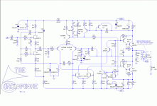
R21= 39K
D8,D9= 15V and 13V
Output transistors = TIP35C
PCB- Alexmm ( without any fuse )
None of these amps have Pot connected to it ,hence volume is controlled through source (Volumio or bluetooth )
All speakers are 8 ohms
Outputs and drivers mounted on common heat sink, remained isolated when checked after the incident
LCR meter showed Q8 and Q10 in good health - but I am not very confident on capabilities of this meter.
Want to find out root cause of this problem, not sure where to begin.
Any help would be highly appreciated.
Don't mind rebuilding the entire board with all fresh components (SQ of circlophone is worth every effort) but want to know the root cause
Regards
Goutham
Hello Folks !
By mistake switched on my set up with full volume, one mid range channel went up in smoke
. later inspection revealed burnt R10 (15 ohms resistor ) and completely charred 10 ohms 3W resistor connected in series to output. No visible damage whatsoever on remaining 4 circlophones - they are running just like before.
This is happening 2 nd time . what could be the reason for this
Last time also it was single channel in mid range when CD player which was connected, started with full volume by mistake.
My setup :
Source: Raspberry pi with Alloo boss DAC running volumio OR Bluetooth receiver
linkwitz riley 3 way active crossover (published in silicon chip magazine)
Total 5 circlophones -
2 for each channel of high frequency- sharing single power supply of +- 28V DC (20-0-20, 5A transformer )
2 for each channel for mid range frequency- sharing single power supply of +- 28V DC (20-0-20, 5A transformer )
1 for low frequency with Power supply of +- 28V DC (20-0-20, 5A transformer )
total 3 separate enclosure and 3 transformers and power supply.
Grounding : Common ground(Left and right channel power ground and speaker returns are connected) per enclosure where RCA input sockets are not isolated from the chassis. (left and right channel signal grounds are connected )
Above set up was running without a glitch for almost last 4.5 months.
R21= 39K
D8,D9= 15V and 13V
Output transistors = TIP35C
PCB- Alexmm ( without any fuse )
None of these amps have Pot connected to it ,hence volume is controlled through source (Volumio or bluetooth )
All speakers are 8 ohms
Outputs and drivers mounted on common heat sink, remained isolated when checked after the incident
LCR meter showed Q8 and Q10 in good health - but I am not very confident on capabilities of this meter
.Want to find out root cause of this problem, not sure where to begin.
Any help would be highly appreciated.
Don't mind rebuilding the entire board with all fresh components (SQ of circlophone is worth every effort) but want to know the root cause
Regards
Goutham
This should pose no problem, except perhaps for your speakers and your ears.Hello Folks !
By mistake switched on my set up with full volume,
This looks like a violent load-dumping event. It could happen in case of severe clipping and highly reactive speakers.later inspection revealed burnt R10 (15 ohms resistor )
A fix would be the addition of anti-kick-back diodes across the C & E of each output transistor; 1N4004 are sufficient, but you can also opt for larger (3A) diodes and fast types. Connect them with the cathode to the collector obviously
Which resistor are you talking about? There is normally only the zobel in series with the output, and it is shunted by a coiland completely charred 10 ohms 3W resistor connected in series to output.
I do not see any plausible explanation other than load-dumping: almost everything else would have ended with the OP devices shorted.Want to find out root cause of this problem, not sure where to begin.
Any help would be highly appreciated.
Don't mind rebuilding the entire board with all fresh components (SQ of circlophone is worth every effort) but want to know the root cause
Note that they might be damaged, even if they are not short-circuited: the reverse bias of the E B junction is not healthy.
In summary: replace OP and drivers as a precaution, and add diodes to all your modules, including the ones that were unaffected.
- Home
- Amplifiers
- Solid State
- Building Elvee's Circlophone: Documentation, Parts, Accessories, & beginner friendly