If you have hum then realistically its a ground loop. The fact that when you disconnect the LS ground and still have music means that the ground part of the signal is still getting to the LS.
Think of 2 separate "grounds". One is the signal ground. the other is the safety ground or "earth". This earth is connected to the chassis and the ground pin of the IEC. The signal ground and earth are only connected at one junction, and separated by either a CL60 or 2 diodes (cheapy 1n4007 are AOK) wired 69 style, and then with a ~10R 5W resistor and 0.001-0.01uF >250V cap in parallel.
If you can configure it that way then you will have zero hum. But you must make sure signal ground doesn't contact the chassis anywhere.
Fran
Last edited:
Thanks for your help Woodturner-Fran...Ive been trying hard to think where the signal grounds could be in contact with the chassis...is it posible that the metal standoff's im using for the boards are somehow causing this? coz apart from that i really cant think of anything else 
Is there anything i could check with my Mutimeter Continuity function?
Alon
Is there anything i could check with my Mutimeter Continuity function?
Alon
The signal lines coming in from the RCAs are not screened and not twisted.
This is one of the biggest problems with two channel amplifiers. How does one connect the source to the power amp and maintain an interference free connection from source to power amplifier through a pair of spaced apart RCAs?
Those two loops that are visible would be excellent aerials for transformer hum and EMI.
But the buzz is also a clue. It may be a PSU grounding error. Where is your main Audio Star Ground?
Does anyone know of a supplier other than Selectronique for R core transformers. I was going to order 2 because they seem to be the transformer of choice for the DCB1 but selectronique want payment by bank transfer which means an extra 30% on the bill! Thanks in advance.
Marra
Marra
Does anyone know of a supplier other than Selectronique for R core transformers. I was going to order 2 because they seem to be the transformer of choice for the DCB1 but selectronique want payment by bank transfer which means an extra 30% on the bill! Thanks in advance.
Marra
I've buyed from Selectronic with Credit Card, I don't remember if via PayPal but I'm sure of it...
The signal lines coming in from the RCAs are not screened and not twisted.
This is one of the biggest problems with two channel amplifiers. How does one connect the source to the power amp and maintain an interference free connection from source to power amplifier through a pair of spaced apart RCAs?
Those two loops that are visible would be excellent aerials for transformer hum and EMI.
But the buzz is also a clue. It may be a PSU grounding error. Where is your main Audio Star Ground?
Hi Andrew, thanks for your help. The signal lines are a twisted pair, the only ones that ar'nt are the dcb1 output to output rca's as the wire are very short.
I have attached a labeled picture of my build, hopefully it will be more clearer as to whats happening with my build.
An externally hosted image should be here but it was not working when we last tested it.
I also found out that on my optivol board, all the signal grounds are connected to each other...Input L/R and Output L/R all connected together.
Is this maybe why when i disconnected the Input grounds(doing this got rid of a loud hum, when chassis ground is connected) i still got sound, because the output grounds are still connected and they are connected to the input grounds on the board??? Have a look at the attached pic...
An externally hosted image should be here but it was not working when we last tested it.
Also i dont have a main audio star ground?? i thought that this would be done on the boards...how would i do this??
Thanks for your help.
Alon
I would try to change a the fan for a better one. That is a really improvement, audible for any person, even if they don't know anything of HIFI they will be able to discern a clearly decrease in enviromental noise around the equipment.I wasn't expecting an improvement in SQ, i only did it because (1) I had a spare Shunt Reg and (2) I read somewhere that a clean power supply can help keep a fan quiet...so i thought id give it a go...
And a very important thing, run it below 12v. 9v is ok but you can go lower. This bring the most important improvement in noise. Try it with a pot to control it.
Connect the CL-60 between the earth ground that comes from the IEC and the central ground of the DCB1 power supply, that's between the two big filter capacitors. The connect the ground from the IEC to the chassis. The rest of the audio input or output or Optivol grounds should be disconnected and isolated from the chassis. This point is very important.
Check with the DMM in continuity mode if there is a short between the RCA connectors and the chassis. It should have nearly the same resistance than measuring the CL-60 alone.
Yoour main star gorund should be between both big capacitors of the DCB1
Regards,
Regi
I've buyed from Selectronic with Credit Card, I don't remember if via PayPal but I'm sure of it...
Thanks for that. I emailed them because I don't sepak or read french and they got back to me saying payment to be by bank transfer. I've sent them another mail so hopefully they'll let me pay by paypal.
But the buzz is also a clue. It may be a PSU grounding error. Where is your main Audio Star Ground?
no...............Your main star ground should be between both big capacitors of the DCB1
That puts the charging currents in with the audio currents.
The main star audio ground MUST NOT be between the the main smoothing caps.
The Main Audio Star Ground can be after a short link from the main smoothing cap Zero Volts. Even 1mm of short link would do the job properly. MyRefC v1.3 uses the length of the plated through hole on the PCB as this separating link. It's just like Sugden have used, 1.6mm long and perfect separation.
mmm. Its a ground loop surely. What I would try next is to line up the ground tags on your input and output RCAs. Solder a ground bar along all the tags (so all 4 ground tags linked up together). Something like a short piece of 2.5mm sq copper is good.
Then bring 1 wire from the LS ground to the bar, I wire from the hypnotize ground to the bar and then connect that bar to the IEC/chassis ground through the back to back diodes//power resistor//cap as described earlier.
Fran
Then bring 1 wire from the LS ground to the bar, I wire from the hypnotize ground to the bar and then connect that bar to the IEC/chassis ground through the back to back diodes//power resistor//cap as described earlier.
Fran
My DCB1 Blue Edition Build
Hi guys,
I have a question for you:
Here is the background,
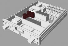
1 - I want a compact build, soi chose a HiFi 2000 Galaxy box !
2 - I want a digital input/volume selector with a log relay volume control.
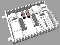
3- to keep things quiet i choose a R-core tranformer .......this is the start of my dilema...:
should i have transformer inboard or will it interfere too much, from images you can see the reason for my hesitation, the output RCA pair is close to the AC wiring.
I can shield this but the question remains ....will it be enough ?
Glad for all sugestion I'm still at the stage of milling the front and other bits.
Hi guys,
I have a question for you:
Here is the background,
1 - I want a compact build, soi chose a HiFi 2000 Galaxy box !
2 - I want a digital input/volume selector with a log relay volume control.
3- to keep things quiet i choose a R-core tranformer .......this is the start of my dilema...:
should i have transformer inboard or will it interfere too much, from images you can see the reason for my hesitation, the output RCA pair is close to the AC wiring.
I can shield this but the question remains ....will it be enough ?
Glad for all sugestion I'm still at the stage of milling the front and other bits.
Attachments
The R-Core will not interfere significantly but the AC cord and primary cabling can bring some more mains frequency when near to the RCAs. I had one measured built with a narrow back panel and AC coming in likewise. I could see 50Hz higher on FFT than normal, but was inaudible on the speakers. It did not use coaxial in/out cabling though. It was a Mezmerize, so the naked portions were short.
Well today i found out that one of the holes i drilled for the rca's(the left input) was a little too small, and so the ground part of the rca was touching the chassis...because the grounds are all connected on the optivol board, in effect all rca's were shorted to the chassis, and connecting the chassis to earth caused a huge hum...which is why when i disconnected the input grounds this problem disapeared. So i used some electrical tape to isolate the offending rca from the chassis, reconnected the input grounds to the optivol board. Now all rca's are isolated from the chassis
Switched on to test...the good news is that the loud hum has gone...but i still get the quiet Hum and buzz. So i guess the next step is to attached the CL60 from the earth(IEC) to the main star ground point. Could i also connect the signal grounds to the earth(IEC) via a CL60? or should i use the ying yang diode method?
While i await delivery of the CL60's, is there anything else i should look at doing???
Thank you ALL for your help...it is much appreciated
Btw Teabag, yes those are Z-foils, and i LOVE what they do to the sound...or what they dont do
Alon
Switched on to test...the good news is that the loud hum has gone...but i still get the quiet Hum and buzz. So i guess the next step is to attached the CL60 from the earth(IEC) to the main star ground point. Could i also connect the signal grounds to the earth(IEC) via a CL60? or should i use the ying yang diode method?
While i await delivery of the CL60's, is there anything else i should look at doing???
Thank you ALL for your help...it is much appreciated
Btw Teabag, yes those are Z-foils, and i LOVE what they do to the sound
...or what they dont do Alon
Good progress Malka07.
I don't really have much of an opinion of the CL60 vs diodes - I've just always used diodes as I have plenty of them to hand (same with the caps etc) from pulls from old equipment.
One thing to check - is this hum with the source connected or not? My DCB1 buzzes at a very low level until the relay clicks, connecting the source. I only noticed this when I was trying out a power amp with higher gain than my others. Might be worth shorting the inputs and making sure its not somethign coming through from the source.
Fran
Then put the output pair on the opposite side, and start connecting the inputs by the other side.should i have transformer inboard or will it interfere too much, from images you can see the reason for my hesitation, the output RCA pair is close to the AC wiring.
I can shield this but the question remains ....will it be enough ?
The Main Audio Star Ground can be after a short link from the main smoothing cap Zero Volts. Even 1mm of short link would do the job properly. MyRefC v1.3 uses the length of the plated through hole on the PCB as this separating link. It's just like Sugden have used, 1.6mm long and perfect separation.
Hi Andrew, i have attached a pic...is this the correct place to connect the CL60 to?????
An externally hosted image should be here but it was not working when we last tested it.
Thanks
Alon
Malka, your audio ground and your main star ground are already connected between them. Just connect the main ground to the chassis through a CL-60, thus both grounds are tied.
Thanks Regi...i will do this as soon as the CL60 arrives...btw could i test this with just a 10ohm resistor? or does it need the ying yang diodes and cap?
Alon
the third wire in the mains cable, known as Earth wire and Protective Earth must be connected to chassis. not anywhere else. A Permanent bolted or welded connection to chassis.connect the main ground to the chassis
Then connect all other external conductive parts to chassis. That is what Regi told you, when he said "connect the main ground to the chassis"!
- Home
- Amplifiers
- Pass Labs
- Building a symmetrical PSU B1 buffer