![Selector_position[1].jpg](/community/data/attachments/137/137485-072309e11040c29ffaea0bdcfb31bc62.jpg)
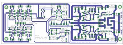
The pin outs shown printed on the board are not correct! They are as in my post Gnd, 6, 1, 5, 2, 4, 3 in that order from shunt side to relay side of the board. Thats the order of the relays as they are routed to the connector. (I am sure you know this already") )
)
)
Last edited:
The pin outs shown printed on the board are not correct! They are as in my post Gnd, 6, 1, 5, 2, 4, 3 in that order from shunt side to relay side of the board. Thats the order of the relays as they are routed to the connector. (I am sure you know this already
My basic testing last night between 1 and 4 concurs with BillyK.

They are correct if you look at the new overlay and the traces on this overlay here:
http://www.diyaudio.com/forums/showthread.php?p=1909777
The input relays got new numbers to make it match, on the new overlay the input numbers changed, now it makes sense so to speak...
http://www.diyaudio.com/forums/showthread.php?p=1909777
The input relays got new numbers to make it match, on the new overlay the input numbers changed, now it makes sense so to speak...
Last edited:
Salas, not fair, you have all the best pics
billyk, here's some more possible info for builders - I think some are going to want to know what is an acceptable DC offset from the B1 buffer. The answer is here:
http://www.diyaudio.com/forums/showthread.php?p=1927645
Some builders might like to know that 5mm LED's need to be raised 6mm (1/4") otherwise they will not fit properly, they might like to know that before they buy their LED's, or maybe this should get a mention in the BOM.
As time goes on I am very happy with the symmetric shuntreg B1 buffer, it may be the mother of all buffers. Very good details and still sounds very smooth is how I would describe it I now realize that running a Lightspeed into a low impedance SS (Tripath) amp was not such a good idea...and the buffer (in my instance) is an excellent solution.
Ian.
billyk, here's some more possible info for builders - I think some are going to want to know what is an acceptable DC offset from the B1 buffer. The answer is here:
http://www.diyaudio.com/forums/showthread.php?p=1927645
Some builders might like to know that 5mm LED's need to be raised 6mm (1/4") otherwise they will not fit properly, they might like to know that before they buy their LED's, or maybe this should get a mention in the BOM.
As time goes on I am very happy with the symmetric shuntreg B1 buffer, it may be the mother of all buffers. Very good details and still sounds very smooth is how I would describe it
I now realize that running a Lightspeed into a low impedance SS (Tripath) amp was not such a good idea...and the buffer (in my instance) is an excellent solution.Ian.
Some builders might like to know that 5mm LED's need to be raised 6mm (1/4") otherwise they will not fit properly, they might like to know that before they buy their LED's, or maybe this should get a mention in the BOM.
As time goes on I am very happy with the symmetric shuntreg B1 buffer, it may be the mother of all buffers. Very good details and still sounds very smooth is how I would describe it
Ian.
3mm 1.8V Leds is the directive. If with 5mm they gotta lift.
Its a smooth little tell it all bugger, init mate?
Ian, thanks for the addition. Time is not mine lately.
Ya, the sound is something, I tried to get a little reading done and made the mistake of putting some music on. It just kept saying Listen to me, listen to me, and that was all I could do, it will just not be ignored!
Ya, the sound is something, I tried to get a little reading done and made the mistake of putting some music on. It just kept saying Listen to me, listen to me, and that was all I could do, it will just not be ignored!
Is the BOM final? will it be published? I searched and have been following the thread but i couldn't find it and I want to order my parts.
I know korben69 has been doing the BOM. I am sure he'll come up with the link shortly.
My only problem with Korben69's latest BOM is the following.
22-01-3037-these connectors have some sort of lip and don't seem to fit. I am going to try work out with mouser what the best connector is.
Yeah I spoke with him regarding that issue, if you are referring to the two little tab thingums on the sides. The 7 pin connectors mate properly and I found Mouser 538-22-23-2031 should be the right male part. Perhaps it would be better to leave the male parts alone and find the suitable female?
Done. I spoke with Mouser Tech. They said Molex 10-11-2033 is the correct part.
From page
http://www.mouser.com/catalog/catalogUSD/639/1452.pdf Column D is correct for the male connectors.
From page
http://www.mouser.com/catalog/catalogUSD/639/1452.pdf Column D is correct for the male connectors.
For Uriah:
See that you have 2V+/-0.3V across R1 combinations. That says the shunts CCS currents are normal.
Check that you hear the output relay clicking one time 3-4 seconds after power on.
See that you have less than +/-5mV DC offset on the audio outputs.
See that you have +Vout a bit more than - Vout.
If all of the above are OK, connect to stereo. Check for ground loops. If the background is silent, play some music.
Post a photo.
You were away, we returned to the original building thread for tips, presentations, anything tech, so to keep the GB thread clean. Anybody that will want to look in the future for the DCB1S will not look in a GB thread intuitively.
You did not report chatter. Relay is silent beyond clicking?
You did not report chatter. Relay is silent beyond clicking?
10.07 and 10.82
2.05 and 2.25
I dont hear the relay but I suppose at this point it seems fine to hook up to the stereo and see. Now I have to get the speakers out of the car.
Oh man its been a morning. My wife blew a tire on the way to work. New tire.. 1 year old. Have been dealing with that and finding a cheap way to fix the rim so I dont have to buy a new one. There is a shop that bends and polishes dents and gouges out of rims so thats good. New tire as well, obviously. Daughter is pretty upset that we arent going to the childrens museum today. So there, I am cranky! LOL
Uriah
Hypnotize as a symmetric shunt
Hello, Here is a quick update on my proto build as a shunt supply. So all of the bits came in this weekend. I mounted everything on the board except the second led string.
Salas , I am ready for coaching.
Currently on the CCS string I have a Vf of 5.6V. Using a 2X15V 50va tranny, I see +/-22.2v after the diodes and 16.65V after the CCS string. I am using a 16R 2W resistor in place of the 2x 68R.
What calculation do I need to use to tweak the output voltage to +/-15V? Most of my LEDs measure 1.8 to 1.95 vf. Should I start with a 4 LED string and report back?
Thanks, Nick
Hello, Here is a quick update on my proto build as a shunt supply. So all of the bits came in this weekend. I mounted everything on the board except the second led string.
Salas
, I am ready for coaching. Currently on the CCS string I have a Vf of 5.6V. Using a 2X15V 50va tranny, I see +/-22.2v after the diodes and 16.65V after the CCS string. I am using a 16R 2W resistor in place of the 2x 68R.
What calculation do I need to use to tweak the output voltage to +/-15V? Most of my LEDs measure 1.8 to 1.95 vf. Should I start with a 4 LED string and report back?
Thanks, Nick
- Home
- Amplifiers
- Pass Labs
- Building a symmetrical PSU B1 buffer