Thanks Kannan, the buffer looks really good but why all the LEDs and if put in a case, you can't see them lights. Is there other purpose for the LEDs? Would like to purchase 1 board.
The power supply is a shunt and LEDS are used for voltage references in the regulators as they are low noise/economical -than zeners at low voltages. You can check Group Buy thread for placing your requirements. there are two boards - one with 6 input relay source selection /volume control /output relay while switching on etc. Powersupply is a very stable low noise shunt regulator worth trying for other applications - probably you would like to have more boards
kannan
Again, thanks for the info Kannan. I have put in for 2 of each boards. What is the 'LDR' to be include?
I really don't know but I think some people want light speed attenuators in place of Volume control - which uses LDR's
Kannan
Does the above 'risk' still exist in this buffer?
Only in case that one psu fails. The resistor across input safeguards against a dodgy pot with future wear. Use sinks on the mosfets, and the rest of longterm failure risk is yours if you want to use a DC coupled amp as well without any DC sensing protection.
You can build a DC sensing / off set protection circuit - to avoid this problem. Power amps generally should have either a coupling Cap in most of the cases or should have a DC sensing /shut off system if it is DC coupled to the speaker.
kannan
Does the DIY Alephs have this or have anyone done one? Thanks.
There are several output DC protection circuits and kits if you google. Also here if you search. The simplest protection possible, would be to introduce a good quality coupling cap in the input of the amp only. You avoid many before, so its a logical compromise. Its fail safe in the long run too.
Some building and cct operation hints have been poping in the sister GB thread, I copy here for the record:
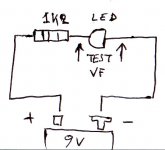
''A little Led info. I run a little test on red, green & yellow, under 2Vf Leds. If with a DVM that gives them under 1mA on diode Vf test (not all got such function), the reds add up +20% Vf at 6mA, the greens +10%, the yellows +13%. So you can measure 2-3 from each color of your stash and see if they follow each other's gain VS 9V battery +1k test (mine did), match with the DVM but know the final total by jotting down the Vf % climb at more mA. 6mA isn't random, I have seen that 2SK170s hover around 70% of their 9-10V Idss when under 0,6Vbe. Because the bulk of BL from Spencer seem to fall between 8-9mA Idss, 8.5*0.7=5.95. Hope this helps.''
''Note for those who fancy the Hypnotize as a symmetric shunt reg board mainly:
As I have posted enough times before, this symmetric shuntreg has tunings for the DCB1 and will perform its best as a pair. It will work as a general shunt very well, but bear in mind that it is optimized for DCB1. It has a purpose built Vref current assymetry. Specifically I exploit the njfet's assymetry to run the positive voltage reference harder than the negative, in order to match the step responses of the two sides. The positive Mosfets have different drive optimization and damping needs than the negative ones in conjunction with differences between their NPN/PNP drivers. You will invariably see a 2.5-3% +V prominence in average with matched leds. This is due to they run harder in the plus side. The slight Vout assymetry helps find better DC offset by swaping audio side njfets that are not terribly close by nature. Its economic, intuitive, does not take much knowledge or special rigs. There are positive subjective findings also about the whole evolution of the DCB1's pairing regs and my final choices, but I will leave that out, its wacko enough as a basis of technical conduct.
So, in a nutshell:
1. You use the regs for the DCB1 as it comes on the boards, fine. Forget about it, enjoy some tunes. Done the weird part 4U.
2. You want very close +/- symmetry for some reason? Only for other applications than the DCB1, up R5 on the positive side until they meet. Best will be half road. Use somehow less Vref total leds on the + side's 5 string Ref, and up its R5 a bit. It works like a faucet for the njfet under vbe and the mV across it.
3. Want more ICCS current for another application? Lower R1's. (3LedsVf-Vgs)/R1=ICCS. As it is, it should run 60-70mA. You may need +20% of the Ibias on class A circuit feed if conservative, but double or more is a bit better for ample dynamic reserve. It directly hits on dissipation, so sinks or Mosfet assembly underneath PCB a' la power amp style and bolding on metal floor or aluminum bar on insulation pads becomes mandatory.
4. If you want drastically different Vout for other applications, leave less leds in the Vref and add a resistor in the place of the missing one(s). Measure the drop across R5's prior to doing that, derive I, and calculate the resistor needed for target Vout by using Ohm's law. Its Vdrop will add on the remaining Leds. Don't use only a resistor, the less its value the better the damping ability of the Vsource. So leave enough part on the Leds.
5. If you don't dig the above, don't tweak, grab a beer and take it easy.''
''Quote:
Originally Posted by Ian444
I came up with by using the test method from the link above, returned small DC offsets from 0.2mV to 2.4mV.
Pair Idss 7.72/7.73 offset 0.2mV
Pair Idss 9.64/9.65 offset 0.3mV
Pair Idss 8.67/8.68 offset 0.7mV
Pair Idss 7.85/7.90 offset 1.4mV
Pair Idss 8.32/8.38 offset 1.4mV
Pair Idss 6.74/6.82 offset 2.4mV
Swapping the positions of the upper and lower 2SK170 often changed the DC offset by about 0.2mV,
you are measuring Vgs. That is not quite the same as output offset.
But, it does allow a comparison.
Take the first three pairs.
Your measuring of Idss indicate that each pair have a mismatch of 0.01mA. That is 1part in many hundreds. i.e. a lot closer than <=0.3%.
Look at the Vgs variations. 0.2mV to 0.7mV. There is little correlation between the <0.3% selection and the output offset. That tells me the Idss was not measured to better than 0.3% it was more likley that it exceeded 2%. Now take these three pairs and set them up as an LTP, with the sources connected and the gates connected and now measure the volts drop across the 1k0+-0.05% load resistors. Connect gates to sources so that each half of the LTP is passing Idss. I guarantee that your load currents for all three pairs will not match to better than <=1%. i.e. your initial selection of 0.01mA is only good for batching into similar groups. Our DIY methods of measuring Idss and other parameters are flawed when attempting absolute measurements. That's why I compare one (DUT) against another (REF), I cannot achieve accuracy for absolute measurements and recognising this means I never fall into the trap of claiming absolute accuracy of my measurements.
Now look at the gross range of your six pairs. Here we can se the trend of rising Vgs as Idss difference increases. That conforms that the method has some reproducability. It is not worthless, just don't rely on it for absolute measurement.
The biggest problem as I see it, is holding Tj=25degC. I can never achieve that.
A final reminder.
The B1 does not need matched pairs. It simply requires selection of similar Idss pairs.
Any amateur measurement procedure with a bit of care can achieve that.
__________________
regards Andrew T.''
''Get a 9V battery and 1k2 resistor. Do that on the pic. Your test Vf is going to be more representative of final use since it simulates 5-6mA.
Mixing is OK. There's no Led problem you can't fix''
Attachments
Does the above 'risk' still exist in this buffer?
Every DC amp circuit has this risk and it is a design feature ;-) So while we generally want to avoid caps as much as possible it can be very wise to have only one cap in the whole set by means of a input cap at the power amplifier input as that one can possibly amplify DC ( caused by failure of DC coupled preamp, cdplayer etc) that will destroy your speakers.
But .... 99 % of equipment is AC coupled which you can check looking for an output cap. This practically means (in most cases, just check) that only the symmetrical B1 is a small risk for your power amp and speakers. Being a careful builder I'll take that risk.
Last edited:
it can be very wise to have only one cap in the whole set by means of a input cap at the power amplifier input.
is there any real difference between an input cap on the power amp and an output cap on the preamp? I suppose an input cap on the amp would be more likely to catch user errors (me!)
is there any real difference between an input cap on the power amp and an output cap on the preamp? I suppose an input cap on the amp would be more likely to catch user errors (me!)
You answered it yourself. If you have one guard only, better post him at your main gate.
Any DC line circuit would also need a sizeable output cap because it may be called upon driving different amps with a range of input impedances and must always cater for the lowest imaginable. This ups the cost, worsens the cap. Then it is likely that the most amps gonna have the cap and you double for no reason. Invariably will be as big as needed and no more, bcs the amp's impedance is known to its designer and he maybe had reasons for his chosen RC ms number.
P.S. If the DCB1S sees a large DC input, a. It will not boost it. b. If its as large as one of its V regs, it will just latch there and show it on its output. That is the max it can do. It will not destruct itself, there is no special reason to not survive such.
Now that the GB is in full swing and we can expect to be getting our boards in a few weeks here is the "Construction" aspect of it all.
First we will start with Ian444's excellent compilation:
1. WHAT RESISTANCE VALUE POT SHOULD BE USED?
I forgot to mention that i used 10K Alps Volume pot ( do I have to change it to 20K as originally recommended?)
kannan
20k will be easier on your sources. Sweet spot value for being drivable enough and good on what DCB1 likes to see.
Salas.
Is it also possible to go outside those values, eg a 50K ALPS??
I can get an 20K ALPS, but at 2 times the cost of a 50K. (different shop, different prices.....)
cHoc
Don't. It will work but we don't want such impedance. It will hinder the quality you can attain. In any case if you must, you should make the 220k resistor a 520k one.
No changes if you use the Lightspeed and it is between 10-20k.
If with no pot, you should change the 220k down to 22k across the input. You can parallel 22k-27k underneath pcb at the 220k and take it out later.
Salas.
For correct orientation of the pot see: http://www.diyaudio.com/forums/showthread.php?p=1934234
_________________________________________
2. MATCHING THE LED STRINGS
Your goal is 9V total for Vref string and 5.4V total for CCS string.
So match your Vref strings by testing your leds with 5-6 mA. Try to get elements that add up to about 9.4V for a row of 5.
Salas.
NOTE: Salas recommends using a 9V battery and a 1K2 resistor to test the forward voltage of each LED independently.
NOTE2: The Vref string is the string of 5 LED's, the CCS string is the string of 3 LED's.
__________________________________________
3. MATCHING THE 2SK170 PAIRS IN THE B1 BUFFER
the FETs and BJTs do not need to be matched.
All you need are two pair of B1 FETs (one pair/channel) that have similar Idss.
The B1 buffer has two jFETs, the 2sk170.
They run at roughly Idss.
Select the pair to have similar Idss and the lower run then biases the upper one.
That's all that is required.
None of the other active devices in the regulator nor in the selector stages needs any form of matching nor precise selection.
The LEDs should be chosen to give the required PSU voltages.
Idss within 10% would work.
Within 5% will get closer to what Nelson Pass has recommended.
Within 2% is near perfection.
Within 1% is so tight, many of us cannot measure Idss to this accuracy AND hold all the other parameters at the correct values. I certainly can't. I doubt whether I can measure an absolute 5% tolerance for Idss.
Selecting 9mA+-0.3mA is probably good enough for the B1, but 8+-0.3 will work just as well and so will 10+-0.3
A final reminder.
The B1 does not need matched pairs. It simply requires selection of similar Idss pairs.
Any amateur measurement procedure with a bit of care can achieve that.
AndrewT.
_________________________________
NOTE: a simple method for matching the 2SK170 that may be good enough for the purpose:
http://www.diamondstar.de/transistor_matching_jfet.html
___________________________________
4. BUILDING TIPS
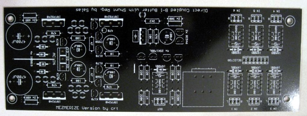
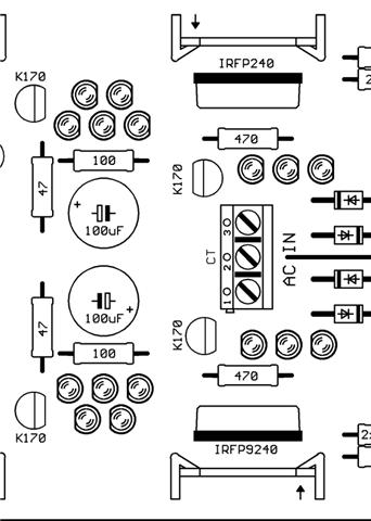
PCB pics:
http://www.diyaudio.com/forums/showthread.php?p=1937486
Overlay1:
http://www.diyaudio.com/forums/showthread.php?p=1909777
Circuits:
http://www.diyaudio.com/forums/showthread.php?p=1932001
- start with the lowest profile components, i.e. resistors, and work up from there.
- the resistor and LED pads are a little bit smaller than some builders prefer, so take care with these pads. Best to double check your resistors with a multimeter before soldering them in, to avoid removal later.
___________________________________
5. HOW TO KNOW IF THE CIRCUIT IS WORKING PROPERLY AND WITHIN LIMITS
In general, if its not noisy, too hot, or having high DC offset, and the +reg is 3% more on average fro matched leds on both banks and between them, plus side R5 has more mV than neg side, is good to go.
Salas.
You will always check the drop across the R1 you calculated for use. IR1=ICCS=VdropR1/R1. That will be your experimental confirmation if you look to alter the current for any use, or relax a bit some excess if your leds batch is high and/or Mosfets batch Vgs low.
Salas.
DaveM it looks great. .5v difference between the sides seems to be normal for this build so you are in spec with that. I too find my 1st set of FETs run a bit hot I put some small sinks on them and the seem happy now.
billyk.
Everybody is getting similar 10.9V and -10.5V range ie one side is about 0.5 V higher than the other leg - it does not affect buffer offset. Also the Mosfet can be held for 5 seconds without pulling out- you do not need heatsink for functioning. However placing a heatsink does not do any harm either. It is good to go -
kannan
___________________________________
6. BOARD SIZE AND OUTPUT IMPEDANCE
Hypnotize basic board is 127X68.58mm
Mezmerize is 197.49X68.58mm
Output impedance: Has a 220 buffer resistor +30 to 40 2SK170BL internal = 250-260 Ohm output impedance and Idss current drive capability. 8.5mA BL mean average in my zip bag.
Salas.
___________________________________
7. NOTES ABOUT USING THE HYPNOTIZE AS A SYMMETRIC SHUNT ONLY
Note for those who fancy the Hypnotize as a symmetric shunt reg board mainly:
As I have posted enough times before, this symmetric shuntreg has tunings for the DCB1 and will perform its best as a pair. It will work as a general shunt very well, but bear in mind that it is optimized for DCB1. It has a purpose built Vref current assymetry. Specifically I exploit the njfet's assymetry to run the positive voltage reference harder than the negative, in order to match the step responses of the two sides. The positive Mosfets have different drive optimization and damping needs than the negative ones in conjunction with differences between their NPN/PNP drivers. You will invariably see a 2.5-3% +V prominence in average with matched leds. This is due to they run harder in the plus side. The slight Vout assymetry helps find better DC offset by swaping audio side njfets that are not terribly close by nature. Its economic, intuitive, does not take much knowledge or special rigs. There are positive subjective findings also about the whole evolution of the DCB1's pairing regs and my final choices, but I will leave that out, its wacko enough as a basis of technical conduct.
So, in a nutshell:
1. You use the regs for the DCB1 as it comes on the boards, fine. Forget about it, enjoy some tunes. Done the weird part 4U.
2. You want very close +/- symmetry for some reason? Only for other applications than the DCB1, up R5 on the positive side until they meet. Best will be half road. Use somehow less Vref total leds on the + side's 5 string Ref, and up its R5 a bit. It works like a faucet for the njfet under vbe and the mV across it.
3. Want more ICCS current for another application? Lower R1's. (3LedsVf-Vgs)/R1=ICCS. As it is, it should run 60-70mA. You may need +20% of the Ibias on class A circuit feed if conservative, but double or more is a bit better for ample dynamic reserve. It directly hits on dissipation, so sinks or Mosfet assembly underneath PCB a' la power amp style and bolding on metal floor or aluminum bar on insulation pads becomes mandatory.
4. If you want drastically different Vout for other applications, leave less leds in the Vref and add a resistor in the place of the missing one(s). Measure the drop across R5's prior to doing that, derive I, and calculate the resistor needed for target Vout by using Ohm's law. Its Vdrop will add on the remaining Leds. Don't use only a resistor, the less its value the better the damping ability of the Vsource. So leave enough part on the Leds.
Salas.
____________________
Hi Salas
I thought different voltages require Zener in place ( above +/-15V ) of LED as a reference ? I am ordering boards mainly to use Shunt with higher voltage and current and will ask you later on what exactly I can do to optimize but the resistor confuses my original idea of using low noise zener.
Kannan
____________________
You can do both. If the zener is really low noise TC compensated, it has far lower impedance than using a resistor, the resistor guarantees very low noise, and the impedance can be just good enough especially if the target voltage is half made by leds. Also zeners up to 4V7 or 6V2 the most are certainly the lowest in noise of their grade, and you can use them in strings as leds, instead of a single 15Vz. The 100uF bypass in this reg and the DCB1 purpose pcb will not allow you a big bypass cap if the zeners you can find aren't exactly stellar. So, some leds and a resistor are the fastest and easiest but safer combination also, IMHO.
Salas.
______________________
Re: +/-15V conversion:
Originally Posted by npapp:
"Thanks Salas, I do need to adjust the voltage to +/-15V. The current should be fine but I will double check. I plan on either using heatsinks or simply under mounting the fet to my chassis which is a 6mm aluminum plate."
That means you will need 4 Leds plus a resistor instead of the 5th led. You will start with a jumper instead of a 5th led. You will tell me the mV you measure across each 10R between the most left 100uF caps. Then I will determine a resistor per side that will provide the needed voltage drop so to reach a symmetrical +/-15V. It will be running constant current and bcs small its going to contribute maybe less than a led for noise. At such voltage you will surely need to bend the fets towards some sinking or use small individual sinks. I saw that B32s needs +68/-43mA at +/-15V for its analogue stage. You will make the double 68R per side, double 33R 1W. Mount them a bit proud off board on different levels by using more leg length, so air circulates between them and the board.That will give about +/- 150mA. Good headroom and keeps the Mosfet transcoductance alive enough. Your PTX must be 2X15AC, 50VA. I guess it has good chances to be likened on the B32s.
Salas.
And now some photos:


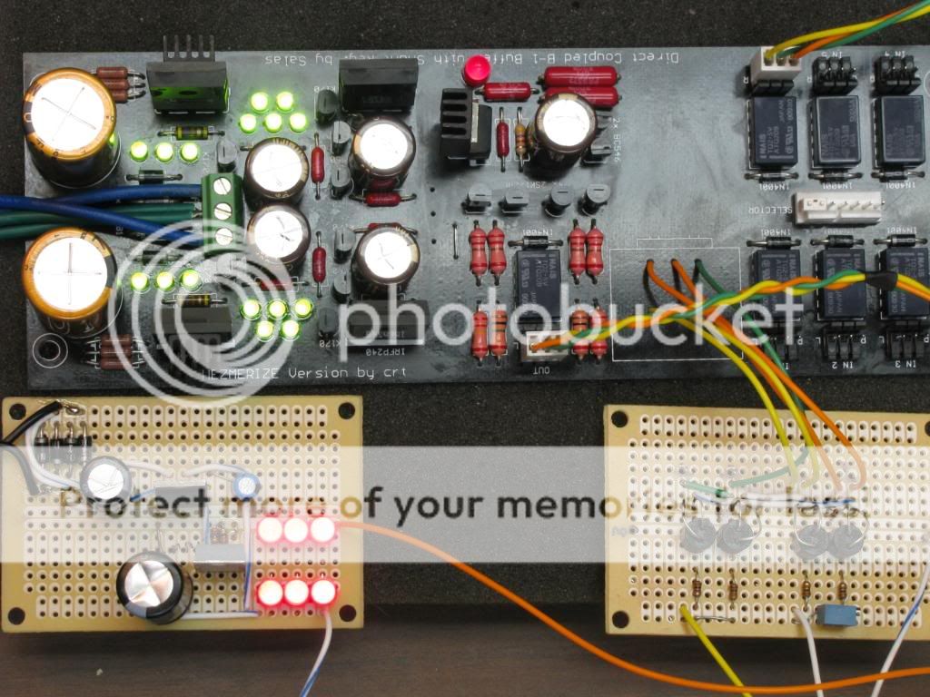
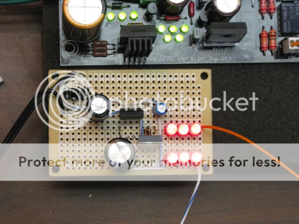

Ok that should get us started. I will comb the other thread for more info and photos and add them. Please feel free to add to this, the more info we have the better it is. We need a link to the BOM.
First we will start with Ian444's excellent compilation:
1. WHAT RESISTANCE VALUE POT SHOULD BE USED?
I forgot to mention that i used 10K Alps Volume pot ( do I have to change it to 20K as originally recommended?)
kannan
20k will be easier on your sources. Sweet spot value for being drivable enough and good on what DCB1 likes to see.
Salas.
Is it also possible to go outside those values, eg a 50K ALPS??
I can get an 20K ALPS, but at 2 times the cost of a 50K. (different shop, different prices.....)
cHoc
Don't. It will work but we don't want such impedance. It will hinder the quality you can attain. In any case if you must, you should make the 220k resistor a 520k one.
No changes if you use the Lightspeed and it is between 10-20k.
If with no pot, you should change the 220k down to 22k across the input. You can parallel 22k-27k underneath pcb at the 220k and take it out later.
Salas.
For correct orientation of the pot see: http://www.diyaudio.com/forums/showthread.php?p=1934234
_________________________________________
2. MATCHING THE LED STRINGS
Your goal is 9V total for Vref string and 5.4V total for CCS string.
So match your Vref strings by testing your leds with 5-6 mA. Try to get elements that add up to about 9.4V for a row of 5.
Salas.
NOTE: Salas recommends using a 9V battery and a 1K2 resistor to test the forward voltage of each LED independently.
NOTE2: The Vref string is the string of 5 LED's, the CCS string is the string of 3 LED's.
__________________________________________
3. MATCHING THE 2SK170 PAIRS IN THE B1 BUFFER
the FETs and BJTs do not need to be matched.
All you need are two pair of B1 FETs (one pair/channel) that have similar Idss.
The B1 buffer has two jFETs, the 2sk170.
They run at roughly Idss.
Select the pair to have similar Idss and the lower run then biases the upper one.
That's all that is required.
None of the other active devices in the regulator nor in the selector stages needs any form of matching nor precise selection.
The LEDs should be chosen to give the required PSU voltages.
Idss within 10% would work.
Within 5% will get closer to what Nelson Pass has recommended.
Within 2% is near perfection.
Within 1% is so tight, many of us cannot measure Idss to this accuracy AND hold all the other parameters at the correct values. I certainly can't. I doubt whether I can measure an absolute 5% tolerance for Idss.
Selecting 9mA+-0.3mA is probably good enough for the B1, but 8+-0.3 will work just as well and so will 10+-0.3
A final reminder.
The B1 does not need matched pairs. It simply requires selection of similar Idss pairs.
Any amateur measurement procedure with a bit of care can achieve that.
AndrewT.
_________________________________
NOTE: a simple method for matching the 2SK170 that may be good enough for the purpose:
http://www.diamondstar.de/transistor_matching_jfet.html
___________________________________
4. BUILDING TIPS
PCB pics:
http://www.diyaudio.com/forums/showthread.php?p=1937486
Overlay1:
http://www.diyaudio.com/forums/showthread.php?p=1909777
Circuits:
http://www.diyaudio.com/forums/showthread.php?p=1932001
- start with the lowest profile components, i.e. resistors, and work up from there.
- the resistor and LED pads are a little bit smaller than some builders prefer, so take care with these pads. Best to double check your resistors with a multimeter before soldering them in, to avoid removal later.
___________________________________
5. HOW TO KNOW IF THE CIRCUIT IS WORKING PROPERLY AND WITHIN LIMITS
In general, if its not noisy, too hot, or having high DC offset, and the +reg is 3% more on average fro matched leds on both banks and between them, plus side R5 has more mV than neg side, is good to go.
Salas.
You will always check the drop across the R1 you calculated for use. IR1=ICCS=VdropR1/R1. That will be your experimental confirmation if you look to alter the current for any use, or relax a bit some excess if your leds batch is high and/or Mosfets batch Vgs low.
Salas.
DaveM it looks great. .5v difference between the sides seems to be normal for this build so you are in spec with that. I too find my 1st set of FETs run a bit hot I put some small sinks on them and the seem happy now.
billyk.
Everybody is getting similar 10.9V and -10.5V range ie one side is about 0.5 V higher than the other leg - it does not affect buffer offset. Also the Mosfet can be held for 5 seconds without pulling out- you do not need heatsink for functioning. However placing a heatsink does not do any harm either. It is good to go -
kannan
___________________________________
6. BOARD SIZE AND OUTPUT IMPEDANCE
Hypnotize basic board is 127X68.58mm
Mezmerize is 197.49X68.58mm
Output impedance: Has a 220 buffer resistor +30 to 40 2SK170BL internal = 250-260 Ohm output impedance and Idss current drive capability. 8.5mA BL mean average in my zip bag.
Salas.
___________________________________
7. NOTES ABOUT USING THE HYPNOTIZE AS A SYMMETRIC SHUNT ONLY
Note for those who fancy the Hypnotize as a symmetric shunt reg board mainly:
As I have posted enough times before, this symmetric shuntreg has tunings for the DCB1 and will perform its best as a pair. It will work as a general shunt very well, but bear in mind that it is optimized for DCB1. It has a purpose built Vref current assymetry. Specifically I exploit the njfet's assymetry to run the positive voltage reference harder than the negative, in order to match the step responses of the two sides. The positive Mosfets have different drive optimization and damping needs than the negative ones in conjunction with differences between their NPN/PNP drivers. You will invariably see a 2.5-3% +V prominence in average with matched leds. This is due to they run harder in the plus side. The slight Vout assymetry helps find better DC offset by swaping audio side njfets that are not terribly close by nature. Its economic, intuitive, does not take much knowledge or special rigs. There are positive subjective findings also about the whole evolution of the DCB1's pairing regs and my final choices, but I will leave that out, its wacko enough as a basis of technical conduct.
So, in a nutshell:
1. You use the regs for the DCB1 as it comes on the boards, fine. Forget about it, enjoy some tunes. Done the weird part 4U.
2. You want very close +/- symmetry for some reason? Only for other applications than the DCB1, up R5 on the positive side until they meet. Best will be half road. Use somehow less Vref total leds on the + side's 5 string Ref, and up its R5 a bit. It works like a faucet for the njfet under vbe and the mV across it.
3. Want more ICCS current for another application? Lower R1's. (3LedsVf-Vgs)/R1=ICCS. As it is, it should run 60-70mA. You may need +20% of the Ibias on class A circuit feed if conservative, but double or more is a bit better for ample dynamic reserve. It directly hits on dissipation, so sinks or Mosfet assembly underneath PCB a' la power amp style and bolding on metal floor or aluminum bar on insulation pads becomes mandatory.
4. If you want drastically different Vout for other applications, leave less leds in the Vref and add a resistor in the place of the missing one(s). Measure the drop across R5's prior to doing that, derive I, and calculate the resistor needed for target Vout by using Ohm's law. Its Vdrop will add on the remaining Leds. Don't use only a resistor, the less its value the better the damping ability of the Vsource. So leave enough part on the Leds.
Salas.
____________________
Hi Salas
I thought different voltages require Zener in place ( above +/-15V ) of LED as a reference ? I am ordering boards mainly to use Shunt with higher voltage and current and will ask you later on what exactly I can do to optimize but the resistor confuses my original idea of using low noise zener.
Kannan
____________________
You can do both. If the zener is really low noise TC compensated, it has far lower impedance than using a resistor, the resistor guarantees very low noise, and the impedance can be just good enough especially if the target voltage is half made by leds. Also zeners up to 4V7 or 6V2 the most are certainly the lowest in noise of their grade, and you can use them in strings as leds, instead of a single 15Vz. The 100uF bypass in this reg and the DCB1 purpose pcb will not allow you a big bypass cap if the zeners you can find aren't exactly stellar. So, some leds and a resistor are the fastest and easiest but safer combination also, IMHO.
Salas.
______________________
Re: +/-15V conversion:
Originally Posted by npapp:
"Thanks Salas, I do need to adjust the voltage to +/-15V. The current should be fine but I will double check. I plan on either using heatsinks or simply under mounting the fet to my chassis which is a 6mm aluminum plate."
That means you will need 4 Leds plus a resistor instead of the 5th led. You will start with a jumper instead of a 5th led. You will tell me the mV you measure across each 10R between the most left 100uF caps. Then I will determine a resistor per side that will provide the needed voltage drop so to reach a symmetrical +/-15V. It will be running constant current and bcs small its going to contribute maybe less than a led for noise. At such voltage you will surely need to bend the fets towards some sinking or use small individual sinks. I saw that B32s needs +68/-43mA at +/-15V for its analogue stage. You will make the double 68R per side, double 33R 1W. Mount them a bit proud off board on different levels by using more leg length, so air circulates between them and the board.That will give about +/- 150mA. Good headroom and keeps the Mosfet transcoductance alive enough. Your PTX must be 2X15AC, 50VA. I guess it has good chances to be likened on the B32s.
Salas.
And now some photos:
Ok that should get us started. I will comb the other thread for more info and photos and add them. Please feel free to add to this, the more info we have the better it is. We need a link to the BOM.
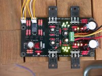
European Hypnotize build.
Just finished building the Hypnotize and no problems to report.
I am using a 6volt NAIS Relay with two 470R resistors dropping the voltage; relay clicks in after a couple of seconds - no chatter no nasty noises.
DC offset on output is .7 and .3 millivolts - I will measure that again sometime.
My initial listening has been done with a BluRay player into the Hypnotize into Stax headphones. Sound is excellent - almost as good as direct into the Stax - this is from cold! Listening to Gotan Project had me bopping around the room - not bad for a 60+.
Components used were for the most part as per the BOM; in the PSU / regulator differences were I used some Green LEDs from RapidElectronics which were all very close to 1.8v measured as per Salas recommendation. 2SK170's were from a batch sourced from Spencer. Resistors were PRP's from PartsConnexion.
In the Buffer I used Takman resistors (from PX) and a Silmic 100uF cap. As mentioned earlier I used a 6Volt relay with two 470R resistors in parallel to drop the voltage after the 12v regulator.
At the moment there are no heatsinks on any devices and they are running warm - however once in a box I may put some on.
Picture attached - hopefully I can add more info on the sound as it breaks in.
Attachments
")
- Home
- Amplifiers
- Pass Labs
- Building a symmetrical PSU B1 buffer