regiregi22 - I believe in an earlier post Salas suggested to try .1 to 1 uF MKP's to replace those electrolytics. The Wima .22 uF being a "known good" part. He had suggested to me to try the Vishays as bypass caps on the existing ones, as those seem highly regarded. Decided to just yank the 'lytics completely. Parts Connexion listed .1 uF as the largest value available. Wanted to target that Wima so another in parallel underneath gives me .2 uF.
I also like the Kester "44", good stuff...
I also like the Kester "44", good stuff...
Another hypnotize lives
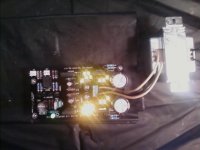
Successful first turn on...
Voltage measured across the the 68 ohm resistors is 2.14
DC offset less than .001 volts. (below what my DVM can measure)
VRef positive is 10.79 V and VRef negative is -10.11.
MOSFET's are just a bit above room temperature.
Not sure if there is any further adjustment required at this point. Only hurdle I had was misunderstanding the suggested transformer type. Fortunately Radio Shack sells an acceptable 12.6V CT transformer that I was able to buy local.
Thanks for the work that went into this. More pics to follow as the project progresses.
Attachments
Macronaut, now it is when the modding time comes 
William, I'm my opinion a film bypass capacitor will perform far better than an electrolytic. But I think that only one capacitor for bypassing some leds is a not very influent in the signal path, so choosing between two high end parts like vishays or wima won't make too much difference. What I say is that both are among the best capacitors for that task, so I don't care too much. I still have to mod mine that way.
William, I'm my opinion a film bypass capacitor will perform far better than an electrolytic. But I think that only one capacitor for bypassing some leds is a not very influent in the signal path, so choosing between two high end parts like vishays or wima won't make too much difference. What I say is that both are among the best capacitors for that task, so I don't care too much. I still have to mod mine that way.
You mean 25V Tx with center tap I guess. All tests indicate success! Let us know how you will like it later when run in your system.
Oops... You are correct. The package says 25.2 Volt, 2 Amp with a center tap.
When I measured the LED's most of them were 1.90 Volts. For a starting point I used the ones that measured the same and got the results I gave above.
Is there any reason to lower the VRef+ to approximately 10.2 - 10.25 Volts? That would be about 1% higher than VRef- which is still at -10.11 Volts. I do not know if it worth doing or not.
No, because it fortunately fixed so well your specific audio jfets for unmeasurable output DC offset as is. I believe that the relay clicks OK? If not, here is the reason of 0 offset success! If it clicks OK its success indeed, and I suggest you give it a listen now.
The relay is working. I can tell that the meter sees some voltage because the display changes between + and - when measuring. And it does briefly show a 1 if I wait long enough. Even after an hour the offset measures the same way.
I think it is time for a beer!
Sorry, I do not have what I need to listen to it yet. I had meant to start with a potentiometer before I connect the Lightspeed control. (already got this from udaily) Perhaps that is better to see if the DCB1 is working like it is supposed to before I connect the Lightspeed. Which is another thing I have to find out how to do, still.
Last edited:
Macronaut, now it is when the modding time comes
You are right, of course. Sheesh, the thing hasn't even been alive for a couple of hours yet. I do mean to use different resistors in a couple of places, though. And I do have a bag of film caps that are looking for something to do. But, probably good to see what I've got before I do that.
regiregi22 - Yeah, I suspect you're probably right. I just picked up those Vishays because it was simple, ordering from one place along with my resistors, and Elna caps. And the fact that they fit the pads. I'll be waiting to hear your impressions about this mod. I'm thinking of possibly going bigger with my heatsinks, and moving the two buffers further apart because of the heat. And possibly running the negative CCS a bit harder.
It will still remain a bit unequal for voltages. He is referring to running currents. Since there are differences in Vgs between PMOS and NMOS batches, same Rset values don't produce same currents in both sides. Gfs will not significantly change if they are already roughly near for current though. Some report very near Rset Vdrop in builds some not. Random.
I think the DCB1's output bias is determined by the Vgs @ Id of the source follower.
If Id is close to Idss then output offset (=-Vds) is near zero. If Id = Idss then output offset is zero. It may wander a little with changes in junction temperature.
I also thought the asymmetric supplies were adopted because some builders thought it made the buffer sound better.
If Id is close to Idss then output offset (=-Vds) is near zero. If Id = Idss then output offset is zero. It may wander a little with changes in junction temperature.
I also thought the asymmetric supplies were adopted because some builders thought it made the buffer sound better.
regi - just to run the two sides equally, right now one is about 170mA, other is ~150mA.
If you will feel any subjective change, please report.
I also thought the asymmetric supplies were adopted because some builders thought it made the buffer sound better.
Indeed.
Did you fix the problem after the spark discharge on the volume knob? Which part was hit?
I've not swapped the FETs out yet.
The last time I did a repair on that board I lifted a trace, even though earlier I was contributing to a discussion on how robust the PCB seemed to have been up till then.
I will start the second board, probably the Mez, with the wireless remote control before I try to "repair" the Hypno. I want to be able to compare and daren't risk losing the first one before then.
- Home
- Amplifiers
- Pass Labs
- Building a symmetrical PSU B1 buffer