Has to do with my suggested log pot value and the way I want to subtly help its balance between channels. 1:10 //.
Yes its very low in ripple. Bigger caps across its Vout just ''slow'' it down. Of course there is enough rectification filtering at 4700uF.
Its interesting when you listen side by side to two so basically same designs but differently executed as a whole. There are so many PCB's given on the GB, that we will possibly get feedback by people having original B1s also. Will be educating on how people perceive or not little stuff in the grand scheme of things.
Thanks Salas, I totally missed the rectification, doh.. was just looking at the shunt reg (should have noticed it was already DC coming in) and that there would be a rectifier and caps before that
")
Andrew, my brute force comment was somewhat tongue in cheek (hence the winking smiley) I'm sure Nelson would not take offence... I do regard it as a simple approach to the problem (which is what Nelson intended I believe) I'd never have considered using such large capacitance on a circuit with such low current draw
I'm interested in doing a symetric PSU for one reason, and that is basically keeping the cost down, as I will probably make a number of B1's as buffers in a line level crossover, either between PLXXO's or possibly some active filters. Being able to leave out the coupling caps should reduce the cost substantially (as I think I will be making at least four), and if I can get away without PS caps on each B1 (locally) by using a high quality PSU all the better I may end up doing something like Salas' original basic regulated supply (using LM's, or perhaps something like Rod Elliot's P05A).. not sure yet, How many B1's would the Shunt supply be able to realistically drive?
Tony.
the regulated supply should be located very close to the B1 and connected with very short wires.
A single pair of dual polarity supplies located remotely supplying various distributed B1s is NOT optimum. It's a complete waste of a regulator circuit.
Have a look at the DCB1 (Hypnotize) for a combined PSU+ B1 buffer.
The buffer (B1) should be located at the output of the transmitter, not at the input of the receiver.
Last edited:
Some people in the USA have their boards - I am in the UK and do not expect them to arrive until at least 2 weeks after they were sent - Customs etc.Has anyone received their boards yet?
Alan
In an effort to save my 2sk170's to what detriment is the j310 in the regulator?? I could find nothing in the thread concerning absolute use of the 170's. If I've missed the obvious I plead for an exemption based on Age, poor eyesight , poverty, Irish ancestors and of course my ex-wife.!!

the regulated supply should be located very close to the B1 and connected with very short wires.
A single pair of dual polarity supplies located remotely supplying various distributed B1s is NOT optimum. It's a complete waste of a regulator circuit.
Have a look at the DCB1 (Hypnotize) for a combined PSU+ B1 buffer.
The buffer (B1) should be located at the output of the transmitter, not at the input of the receiver.
Thanks Andrew, As I was looking to simplify things as much as possible I might go down the path of making a simple regulated supply and sticking with close to the original design B1 simply splitting the supply (to allow exclusion of the input and output caps). The Mesmerize is tempting though for the main control board, ie volume + switching..... I suspect that this (B1) will be a quantum leap over what I already have, so any additional improvements that may be possible will be very small in comparison!
Tony.
Has anyone received their boards yet?
Yes I received my boards earlier this week. Many in the States have received theirs.
Just an update on my proto board build. I ran into some issues with the pot I was using. It appears to cut in and out on one channel and I just decided to replace it with one of the ebay stepped attenuator. I do have the case done. I am missing 3 sets of RCA connectors, but that doesn't stop functionality. I don't really need 3 inputs anyway. So, for now here is my build.
Attachments
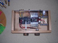
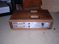
Just an update on my proto board build. I ran into some issues with the pot I was using. It appears to cut in and out on one channel and I just decided to replace it with one of the ebay stepped attenuator. I do have the case done. I am missing 3 sets of RCA connectors, but that doesn't stop functionality. I don't really need 3 inputs anyway. So, for now here is my build.
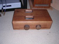
Very nice - beautiful construction . I would have moved the board nearer to back plate to keep the inputs very short. How do you find the sound ? And What size Pot 10K/20K?
kannan
So, for now here is my build.
First one in a custom case! The dice starts rolling, and its a wooden one. Nice work. All best.
Read here some extended view about its sonics. Its from another member, but it will keep you reading something for now.
10-20k will work fine. The sound is very nice, very good in fact. My lightspeed is the best preamp I had heard. Adding this to it took a way a little and gave a little. I hear them as the same quality now with one being better for some music than the other. Soundstage gets W I D E with the DCB1. Clarity is improved over even the Lightspeed. Voices got 2D instead of 3D while depth of the perceived venue increased. Weird but thats the way I hear it. But depth of the venue got really really deep. One recording I felt like I was back 30 rows and then remembered this recording was made from the soundman's seat and it probably WAS 30 rows back. Incredible.
Uriah
Uriah
different FETS
Salas,
I have a few old 2n5566 dual fets I'm thinking of using in your re-designed B1.
Do you think they'll work dropped in without any changes?
Nelson originally spec'd Idss btwn 5-10ma, and 5-30mS for transcond.
The 5566 specs are: Idss 5ma min, 30ma max; and 7mS for transcond.
Thoughts?
Salas,
I have a few old 2n5566 dual fets I'm thinking of using in your re-designed B1.
Do you think they'll work dropped in without any changes?
Nelson originally spec'd Idss btwn 5-10ma, and 5-30mS for transcond.
The 5566 specs are: Idss 5ma min, 30ma max; and 7mS for transcond.
Thoughts?
They surely have compatible characteristics. If you measure their Idss at no more than 10mA (comparable test to 2SKs VDS=9-10V, VGS=0V) for those you have, so their Vt and current through leds is kept at bay, you can set up a dedicated point to point perfboard build I guess. Further I can not predict. Its an experiment you may fancy though.
- Home
- Amplifiers
- Pass Labs
- Building a symmetrical PSU B1 buffer