I bought a batch of 100 from spencer and they ranged from about 6.5 t0 11. 2.2 is definitely very suspect.
Andrew, when did you start using 1R0? Isn't that a tad low? I used a 0.1% 100 ohm resistor and that seems to work quite nicely. Perhaps 100 ohms doesn't give quite enough resolution though for really close matching, a 10 ohm resistor would allow me to use the 200mV range on the multimeter rather than the 2V range... I assume this is the reason for going with such a low resistor value? Or is it because you can just use the reading without needing to divide by the resistance?
Tony.
I agree.
You do need at least 10R0 to get full resolution on most meters.
My initial measurements were taken with only the shunt of the meter as a load.
Before I go tearing into my supplier.
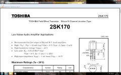
I've just been looking at the datasheet for the 2SK170.
The parameters are quoted at Vds=10V Vgs=0V and Idss=3mA.
That's not too far from what I am seeing.
That is about minimum transconductance expected. 22 milliSiemens is the low side GR(een) grade's bottom Yfs. Anything marked BL(ue) shall vary between 6-12mA IDSS @ 10V VDS with a midway Yfs of 37mS. Else its a bad or fake sample.
Dalbani are being helpful. They are just as stunned as we are that they are being conned.
Check IDSS with this direct method again: http://www.diamondstar.de/transistor_matching_jfet.html
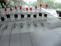
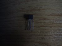
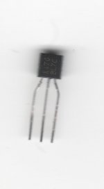
Show us a good macro picture of the JFETS there:
http://www.diyaudio.com/forums/parts/82638-my-transistors-original-copy-44.html
Little Buggers are not easy to photograph.
I've tried my best - see what you think.
They definitely look "brushed" to me. That would be my first clue that they have been remarked.
I've tried my best - see what you think.
They definitely look "brushed" to me. That would be my first clue that they have been remarked.
Attachments
Last edited:
Salas we seem to have two identical threads here.
http://www.diyaudio.com/forums/anal...otrodded-blue-dcb1-build-163.html#post2901795
http://www.diyaudio.com/forums/anal...otrodded-blue-dcb1-build-163.html#post2901795
I'm having a bid of a headache with the delay section.
How much of a delay should this circuit provide ?
For some reason or other the base of my Relay Driver isn't reaching ON for about 10 minutes. If I omit the BC550 I get virtually no delay. I can work around the problem if I could figure out how long the relay should be de-energised for.
The junction of the timing R & C are rising to 12V as I would expect. The issue seems to be the use of the BC550C as a Zener to de-sensitise the relay driver.
I'm not using the BC517 I'm using 2 x BC550Cs connected as a darlington.
Last edited:
- Home
- Amplifiers
- Pass Labs
- Building a symmetrical PSU B1 buffer