Hello!
I've built a p2p DCB1 a year ago, then I moved to another town and had 0 time available for diy. I'm experiencing some humm so I couldn't use the DCB1 all this time, but I hope to address that a bit later. For now, please help me with a few things:
1. For the moment, I'd like to try reducing the R1 value from the current 11ohms. How low would be OK for my transformer to go? (I'm using the Hammond 229D30. 48VAC 30V C.T. @ 1.6A recommended around here) Sorry for such a simple question, but I have basically 0 knowledge in electronics (well, not really 0 but quite close )
)
2. Also, I remember reading somewhere buried in this thread the information that the quality of the resistors in this power supply has no impact on the sound quality, is that correct? Can I use generic ceramic types? On the other hand, I see somebody is using noninductive Mills, so perhaps my memory is playing tricks on me?! Right now I'm using some Dale CFM's.
3. I've ordered the Gigarec pots, a 10K one and a 20K one, just to try them both, so while they're traveling to me I'm trying to find the good quality, suitable 100k and 200k respectively resistors locally. I assume it doesn't matter much if it's 200k or 220k for instance, right? Again, sorry for the "moron-type" question, just wanted to be sure...
4. Finally, how can I tell if my CD player is "happy enough" with a 10k pot? It has a Zout of 500R and I've used it many times for many hours in the past (when I knew even less...) with a couple of mono 1k pots and a pair of 120ohms headphones, so I suppose it has no right to comment on the 10k pot in this case, right? How can one tell if the output stage of the player is "tortured" too much by such impedance values? As long as it sounds good it's ok, or it could still break down one day without any warning?
Thanks a lot!
I've built a p2p DCB1 a year ago, then I moved to another town and had 0 time available for diy. I'm experiencing some humm so I couldn't use the DCB1 all this time, but I hope to address that a bit later. For now, please help me with a few things:
1. For the moment, I'd like to try reducing the R1 value from the current 11ohms. How low would be OK for my transformer to go? (I'm using the Hammond 229D30. 48VAC 30V C.T. @ 1.6A recommended around here) Sorry for such a simple question, but I have basically 0 knowledge in electronics (well, not really 0 but quite close
2. Also, I remember reading somewhere buried in this thread the information that the quality of the resistors in this power supply has no impact on the sound quality, is that correct? Can I use generic ceramic types? On the other hand, I see somebody is using noninductive Mills, so perhaps my memory is playing tricks on me?! Right now I'm using some Dale CFM's.
3. I've ordered the Gigarec pots, a 10K one and a 20K one, just to try them both, so while they're traveling to me I'm trying to find the good quality, suitable 100k and 200k respectively resistors locally. I assume it doesn't matter much if it's 200k or 220k for instance, right? Again, sorry for the "moron-type" question, just wanted to be sure...
4. Finally, how can I tell if my CD player is "happy enough" with a 10k pot? It has a Zout of 500R and I've used it many times for many hours in the past (when I knew even less...) with a couple of mono 1k pots and a pair of 120ohms headphones, so I suppose it has no right to comment on the 10k pot in this case, right? How can one tell if the output stage of the player is "tortured" too much by such impedance values? As long as it sounds good it's ok, or it could still break down one day without any warning?
Thanks a lot!
The DCB1 is a continuous load set by that resistor.
The transformer 48VA 30Vac c.t. has a mximum continuous current rating of 1.6Aac.
When the transformer is feeding a capacitor input filter the manufacturer tells us that the transformer must be de-rated. The factor is usually around 0.7
When you take an output from the rectified and smoothed (capacitor input filter) the voltage is ~1.4times the Vac.
The output voltage for 30Vac will be ~42Vdc after the rectifier.
The voltage before the rectifier will be ~43.4V.
The power available after de-rating is ~0.7*48VA = 34W.
If you know the voltage (or emf.) you can find the maximum continuous DC current is ~34/43.4 ~ 0.8Adc.
Your transformer can supply a continuous DC load current of 400mA (50% of the maximum current rating) and stay cool and more importantly stay reliable.
The standard DCB1 should not be stretched as far as that. 150mA to 200mA is a probable maximum for a hotrodded DCB1.
Thanks a lot for the answer and for the detailed explanation. I hope I'm not too much of a burden with these basic questions, I just don't have the time resources to really learn electronics the way one should before attempting to build amps and stuff.
Could you please explain why 150-200mA should be a maximum for a DCB1? Perhaps it's already been discussed but I haven't found this information and I see people going as high as 500mA or more and reporting sound improvements. My mosfets are heatsinked quite well, I'd say, see pictures here.
Also, please don't forget my other 3 questions.
Many thanks again!
So far it's been a terrifying experience
I guess I underestimate the initial "warning" message on the DCB1. I have the B1 and I built the DCB1 yesterday. Before plugging, I measure the V+, V- to be 10.0 and 10.1 Volt. (Antek 15v 15v, 50Va)
So I think everything is OK.
I used two 25K mono pot. After plugging in, it has a big noise then I smelled something. The amplifier - Emotiva XPA-2 shut down and two tweeters burned.
The second time I plug just one channel, no sound. There are smokes coming out from the Emotiva XPA-2 (just one channel).
The Emotiva XPA-2 still works. It is still under warranty. So I can send it back for a healthy check.
I removed the wiring. So it's just the transformer and the board. I don't think I'll put this beast back in until knowing what's going on. Apparently, not-knowing-what I'm doing has caused great damage to my current system. I'm glad the tweeters are not Scanspeak.
What should I check on the board?
Did you check the DC offset on the audio outputs of DCB1 before plugging in? If there was about DC offset and a DC coupled amp I would expect the woofers to go on the other hand. Did it sound like a squeal? Sad outcome in any case.
Salas,
Thanks for the response. I did not check the DC offset and I'll look into that. Should I just use the DMM I have to check the DC offset from audio output without connecting the volume pots?
It's really powerful... I thought nothing could damage the Emotiva XPA-2.
Have everything pots connected. Use a DMM in DCV on outputs. Is there a chance the pots are reverse connected and it went full tilt? Unbal switch on amp engaged and input RCA used? Its manual says protected against all fault conditions, lets see what went wrong.
I will post a picture or describe how I connect everything. (Again, thanks so much). I was reading Emotiva's warranty today and it did say it protects against all faulty conditions...
I'll have the Emotiva checked and get my system back to normal. B1 still works.
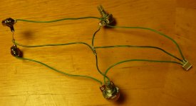
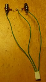
Looks like normal 3in 2out 1gnd pot wiring. Is there a picture of the board also? Offset OK?
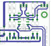
This is the board. All LEDs are lit and the voltage are 10.1 and 10.0.
View attachment 218077
I also heard a "click" after 4-5 seconds (meaning the relay is working). I haven't measured the DC offset yet. I was taking a break from the terrifying experience last night.
Visually it seems normal. I can see the jumpers there too. When you will connect the in & out sockets and see for offset check with the DMM in Ohm mode also that there is earth continuity in all places RCAs & pots that should be. Also see that no 220R position is swapped with 220K by mistake.
Attachments
Visually it seems normal. I can see the jumpers there too. When you will connect the in & out sockets and see for offset check with the DMM in Ohm mode also that there is earth continuity in all places RCAs & pots that should be. Also see that no 220R position is swapped with 220K by mistake.
Salas - I'll be doing some DMM measurement this weekend. I think I finally recovered from the experience. If the voltage between V+, G, V- are 10.1 and 10.0, may I assume the power shunt part is correctly wired and functioned?
Yes, but also check there is voltage drop on the current setting resistors (1.5-2.2V). You report good Vo symmetry as for now. Look for it does not have more than 5mV DC on the AUDIO outputs. The warning about DCB1 is don't use it with DC coupled power amps that sport no DC protection systems just in case it will break down in its life time and will drive high DC in the power amps. A healthy DCB1 with low to almost zero DC offset on audio outputs is as normal to use as any preamp for all intents and purposes beyond that disclaimer. As a matter of fact many here use it on F5 (DC coupled) on own risk for long. Yours is described as a fully protected power amp, no info if DC coupled, and is the only reported bad test incident till now. Can't imagine the reason with no more data yet. Investigate, and good luck.
Salas,
I might have found my problem. The ground wire wasn't secured properly on the input or output.
Anyhow, after I think I "might have" fixed the problem - the DC offset from the output measured at
- 1.1 to -1.3 on both sides when the DMM is set to 200m VDC. I always put the black prob on the "G" positions. Is this correct?
Yes, but also check there is voltage drop on the current setting resistors (1.5-2.2V). You report good Vo symmetry as for now. Look for it does not have more than 5mV DC on the AUDIO outputs. The warning about DCB1 is don't use it with DC coupled power amps that sport no DC protection systems just in case it will break down in its life time and will drive high DC in the power amps. A healthy DCB1 with low to almost zero DC offset on audio outputs is as normal to use as any preamp for all intents and purposes beyond that disclaimer. As a matter of fact many here use it on F5 (DC coupled) on own risk for long. Yours is described as a fully protected power amp, no info if DC coupled, and is the only reported bad test incident till now. Can't imagine the reason with no more data yet. Investigate, and good luck.
Your probe is used fine. If it is -1.1mV to -1.3mV then its very low offset. I would suggest you try to test listen on a secondary cheap system like powered computer speakers. Make sure your source used during the power amp injuring test does NOT have any large DC offset on its audio outputs that DCB1 would have certainly allowed to pass.
Your probe is used fine. If it is -1.1mV to -1.3mV then its very low offset. I would suggest you try to test listen on a secondary cheap system like powered computer speakers. Make sure your source used during the power amp injuring test does NOT have any large DC offset on its audio outputs that DCB1 would have certainly allowed to pass.
Got it. These are the measurement when I turn the 25K volume pot to maximum. My guess the problem is that the negative wire is not touching the center of the three pin connector either on the input or output. It's a bit shaky right now so I'm thinking to solder the input / output wires directly to the PCB. Would that be OK?
With lessons learned, I'll take measure every step changed.
- Home
- Amplifiers
- Pass Labs
- Building a symmetrical PSU B1 buffer


