The veneer is 7 layer at Home Depot.
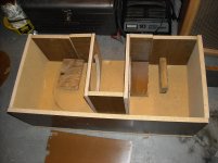
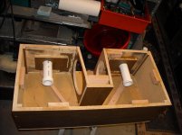
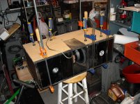
Here is the first mockup. I plan on putting one 1-1/2 dia tube 10cm long centered vertically and horizontally in each side for ports.
Is there any advantage/disadvantage to leaving the speaker plenum set back like it is?
It would seem that the further back it is set, the more of a horn it becomes. I've got a 2-1/2"X8-3/4" coupling channel as it is and for the small 8" speakers this should be overkill compared to the coupling channel I've seen for the 12" and 15" speaker designs.
Comments?
Suggestions?
thanks.
Attachments
Last edited:
Hi,
Don't know if you caught this page in the PPSL thread:
http://www.diyaudio.com/forums/subwoofers/177905-thread-those-interested-ppsl-enclosures-22.html
Some suggestions as to the plenum.
Regards,
Don't know if you caught this page in the PPSL thread:
http://www.diyaudio.com/forums/subwoofers/177905-thread-those-interested-ppsl-enclosures-22.html
Some suggestions as to the plenum.
Regards,
Thanks Oliver. I read about the expanding plenum, but don't have room with only 8-3/4" height and an 8" driver. I'm hoping I can get my hand in there to mount them, else I'll have to mount the drivers before final assembly and plan on not taking it apart again.
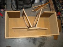
One thought I had was to taper the width instead of the height. ??? Good idea? Bad Idea?
I do plan to camfer the back corners with wedges.
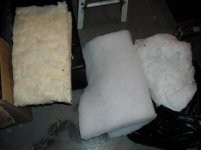
I also have two 8"x14"x1-1/2" sections of acoustic material I pulled from an old set of speakers that I was planning on using. I presume the "back wall" is the wall opposite the drivers (actually left and rt outer walls) and that is where it should go.
One thought I had was to taper the width instead of the height. ??? Good idea? Bad Idea?
I do plan to camfer the back corners with wedges.
I also have two 8"x14"x1-1/2" sections of acoustic material I pulled from an old set of speakers that I was planning on using. I presume the "back wall" is the wall opposite the drivers (actually left and rt outer walls) and that is where it should go.
Hi TheGimp,
Post #25: "...taper the width instead of the height. ??? Good idea? Bad Idea?"
I would try to keep the mouth of the plenum about to the same area as one of the driver's Sd, or whatever is physically possible.
Using acoustic material should be fine as long as it does not interfere with the function of the ports.
Regards,
So, how do I tune this bad boy?
Block off the channel connecting the two sides, and tune each duct seperatly?
Only the side being tuned?
Block off the channel connecting the two sides, and tune each duct seperatly?
Only the side being tuned?
Attachments
Last edited:
Hi TheGimp,
Looks like you're getting there, nice.
Just some quick thoughts: Tune both duct simultaneously, do not block of the air duct between the two chambers. Use any software you like as a guide for a starting point. Model it as a simple bass-reflex enclosure with two drivers, and two ports. You'll have to calculate the internal net volume for the whole box. In general try to get the impedance peaks around Fs to be about the same height for starters.
Regards,
Last edited:
I've run the sim in Hornresp, and AkAbak and have the data from them.
I Plan on running the two speakers (4R each) in series and driving them with a Dayton Audio SA100 (it's not rated for 2R drive, only 4R and 8R).
For testing, since I need a series resistor to measure phase, I will run them in parallel with each having it's own 4R sense resistor in series.
I've got AudioTester which should be able to plot amplitude and phase data wrt frequency.
However if all I'm doing is adjusting the impedance peaks to be the same, I could use two meters to monitor the current through the resistors, and sweep the frequency by hand. Adjust the port tubes one at a time, and when the two meters indicate the same current, the impedances should match.
Right now the prot tubes are cut to 14cm vs the modeled 10cm so I can cut them back. I've got two more tubes cut to 13cm to swap as a start.
the planned procedure is to reduce the port tube length until I start to see a hump at Lf, and go back to the previous length.
Does this sound about right?
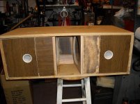
The collars on the ends of the tubes inside the box are to allow me to flair (radius) the insides of the ends.
I Plan on running the two speakers (4R each) in series and driving them with a Dayton Audio SA100 (it's not rated for 2R drive, only 4R and 8R).
For testing, since I need a series resistor to measure phase, I will run them in parallel with each having it's own 4R sense resistor in series.
I've got AudioTester which should be able to plot amplitude and phase data wrt frequency.
However if all I'm doing is adjusting the impedance peaks to be the same, I could use two meters to monitor the current through the resistors, and sweep the frequency by hand. Adjust the port tubes one at a time, and when the two meters indicate the same current, the impedances should match.
Right now the prot tubes are cut to 14cm vs the modeled 10cm so I can cut them back. I've got two more tubes cut to 13cm to swap as a start.
the planned procedure is to reduce the port tube length until I start to see a hump at Lf, and go back to the previous length.
Does this sound about right?
The collars on the ends of the tubes inside the box are to allow me to flair (radius) the insides of the ends.
Hi TheGimp,
I would keep both tubes to the same length, the idea is to keep front and back loading of the drivers as even as possible. Maybe just go with whatever length Hornresp indicates gives the best frequency response, and then give it a listen. It seems that the simulation looks best when the box is tuned to about 38Hz v. Fs=30.2Hz. That would mean that the lower impedance peak will be larger than the upper one.
For a Vrc=39 L, and Ap=22.8cm^2 (2x 1.5"I.D. port tubes) I get Lpt 10" as an optimum (DCS205-4; 2ea in series).
What is the mouth area you ended up with? I like the collars on the inside ends of the tubes.
Regards,
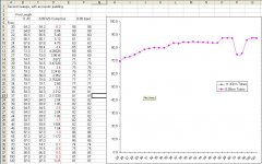
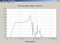
I ran a couple frequency sweeps last night. The last two seemed to be good data.
(1) two different tube lengths
(2) no stuffing yet
I plan on picking up some more pvc pipe today to make some more lengths to try again.
I'm driving the speaker with 1W (2.83Vrms) and slowly sweeping an audio oscillator in 1hz steps while taking readings with a RS Sound Level Meter. readings are at 1M on axis.
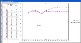
Here is the two sweeps.
Next up is to decide which stuffing to use (Fiberglass, Polymatting, cotton batting), how much, and which walls to place the stuffing on. Then I'll make some flanges for the tubes on the inside. I'll be ready to start measuring again.
Mouth is 5.125" X 8.75" 735cm^2.
I tried measuring the impedance peaks, but could not get a good reading for the upper one. It looked like 17.9 for the lower and 29 for the upper with the long tube. I didn't take impedance measurements with the short tube.
I think the legend is backwards. Upper plot is the long tube, lower plot is the short tube.
(1) two different tube lengths
(2) no stuffing yet
I plan on picking up some more pvc pipe today to make some more lengths to try again.
I'm driving the speaker with 1W (2.83Vrms) and slowly sweeping an audio oscillator in 1hz steps while taking readings with a RS Sound Level Meter. readings are at 1M on axis.
Here is the two sweeps.
Next up is to decide which stuffing to use (Fiberglass, Polymatting, cotton batting), how much, and which walls to place the stuffing on. Then I'll make some flanges for the tubes on the inside. I'll be ready to start measuring again.
Mouth is 5.125" X 8.75" 735cm^2.
I tried measuring the impedance peaks, but could not get a good reading for the upper one. It looked like 17.9 for the lower and 29 for the upper with the long tube. I didn't take impedance measurements with the short tube.
I think the legend is backwards. Upper plot is the long tube, lower plot is the short tube.
Attachments
Last edited:
Hi TheGimp,
Good to see you are making progress.
If possible try running a little higher SPL during your tests. You may look around, and see if you can find some level correction numbers for the RS SPL meter.
Any one of you stuffing choices should work in a subwoofer. I'd go with some kind of polyfill product; keep it even on both sides, and away from the duct openings.
For the mouth dimensions of "...5.125" x 8.75"..." I get 44.84in^2 or 289.3cm^2. That should work just fine.
Getting the impedance peaks is easier using a method one would use to measure T/S parameters, e.g.: Measuring Loudspeaker Driver Parameters. Or, you could use a high value series resistor (e.g.: 1kOhm), and measure the voltage across the driver (the high series resistor will convert your input into a constant current, and the voltage across the driver will be proportional to the impedance).
If you post a picture, e.g.: your picture from Post #28 "Cabinet_Rear_inside.JPG", with dimensions I'll take a look at your internal volume, and add the corrected value into Hornresp. I take it the internal height is 8.75"?
Regards,
I've got to clean rugs today, but once I get them finished (hopefully today) I'll open it up and take a new set of measurements and post pictures.
I'll add fill when I open it.
I bought a 5' section of 1.5" pvc today to use for ducts. On a lark I mic'd the ID. 4.6cm!
1-1/2" is now 4.6cm instead of 3.81cm! I'm sure that has thrown my sims off.
I'll add fill when I open it.
I bought a 5' section of 1.5" pvc today to use for ducts. On a lark I mic'd the ID. 4.6cm!
1-1/2" is now 4.6cm instead of 3.81cm! I'm sure that has thrown my sims off.
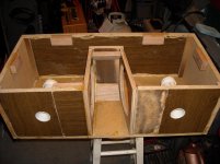
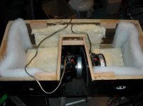
I measured the dimensions again.
I got 8-11/16" Deep, with Chambers that are 10-1/2" by 12-1/2" with the speaker facing into the 10-1/2" depth. So the ports are on a wall facing th 12-1/2" depth.
The rear channel connecting the two chambers is 5" x 3-9/16 and 8-11/16 deep.
The total bracing inside the chambers is 23.36in^3.
I've added padding per the picture, and assemble the speaker with clamps for testing.
I'll put a 1K resistor in series with the speakers and run the impedance test. I was using a 4.7R resistor which was too small.
Attachments
Hi TheGimp,
I have not had any time to look closely at your data, but there is something wrong with the graph in Post #38, those should be two different curves. Make sure that you don't have any air leaks where you're clamping the board. The notch you have from 70-80Hz looks like a room effect. I'd also play around with the measurement setup to see if that makes a difference, sometimes going closer will eliminate room influences.
Regards,
Hi again,
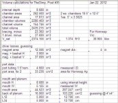
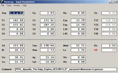
Went through the numbers, and came up with a port of 14cm / 5.5" length. I'll attach the revised Hornresp screens (again, remember that the peak should not be as high), and a screen plot of the spreadsheet:
Regards,
Went through the numbers, and came up with a port of 14cm / 5.5" length. I'll attach the revised Hornresp screens (again, remember that the peak should not be as high), and a screen plot of the spreadsheet:
Regards,
Attachments
- Status
- This old topic is closed. If you want to reopen this topic, contact a moderator using the "Report Post" button.
- Home
- Loudspeakers
- Subwoofers
- Building a sub in a stereo cabinet